Nozzle vane opening limit stop structure for turbocharger
A technology for turbochargers and nozzle blades, applied in the direction of machines/engines, engine components, engine functions, etc., to achieve the effect of light bearing housings, simple shapes, and easy manufacturing
- Summary
- Abstract
- Description
- Claims
- Application Information
AI Technical Summary
Problems solved by technology
Method used
Image
Examples
no. 1 approach
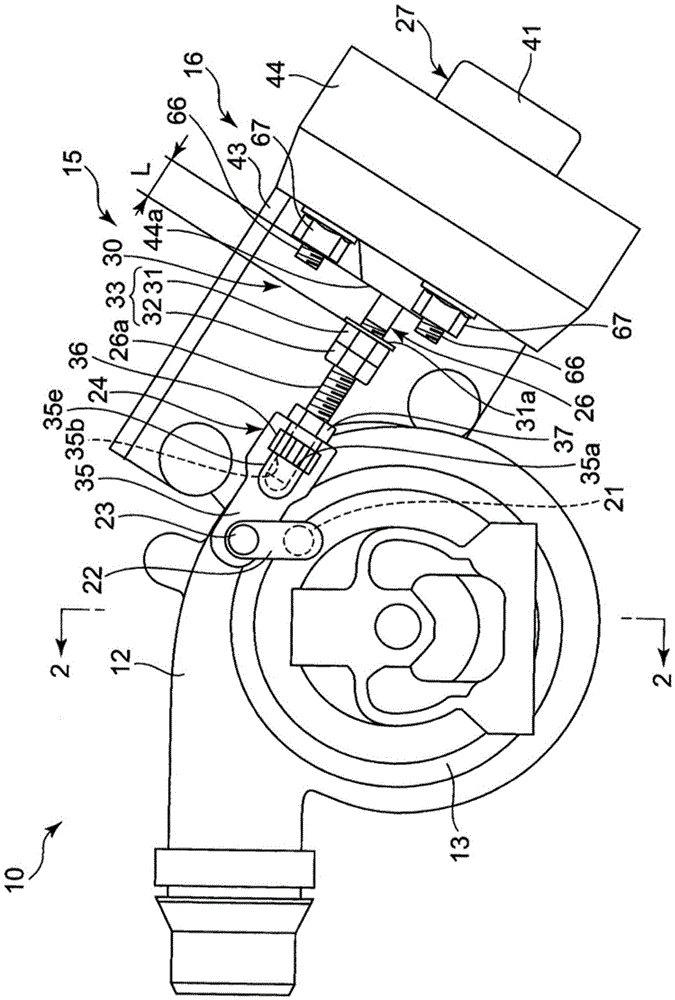
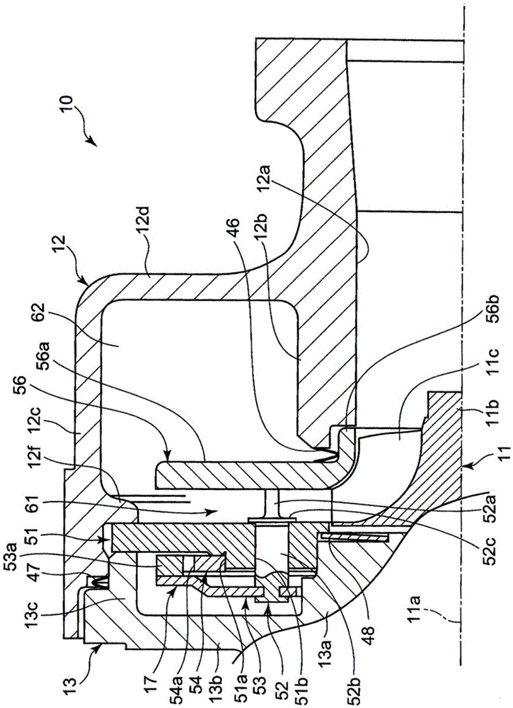
[0049] Such as figure 1 As shown, the turbocharger 10 includes a turbine housing 12, a bearing housing 13, a compressor housing (not shown) and a variable nozzle mechanism 15, the turbine housing 12 rotatably accommodates the turbine working wheel, and the bearing housing 13 is installed on the turbine The casing 12 rotatably supports the rotating shaft of the turbine impeller, and the compressor casing is mounted on the opposite side of the bearing housing 13 from the turbine casing 12 (the front side of the page), and the variable nozzle mechanism 15 can utilize a plurality of nozzles. The vanes adjust the velocity of the exhaust gas flowing into the turbine wheel.
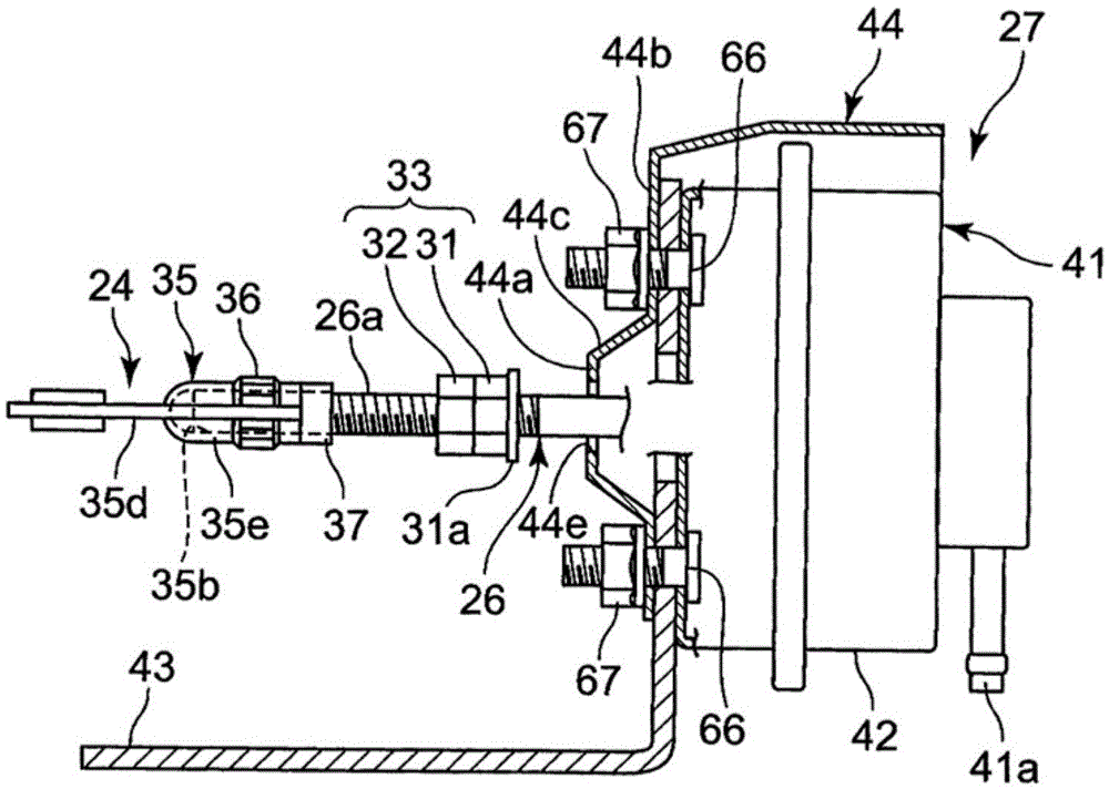
[0050] The external actuator side assembly 16 of the above-mentioned variable nozzle mechanism 15 is composed of a support shaft 21, an outer rod 22, a length-adjustable connection mechanism 24, and an actuator 27. The support shaft 21 is connected to the nozzle vane side. And rotatably supported on the bearin...
no. 2 approach
[0086] Regarding the second embodiment, the same reference numerals are attached to the same structures as those of the first embodiment, and detailed description thereof will be omitted.
[0087] Such as Figure 6 As shown, the connecting mechanism 70 connecting the connecting pin 23 and the actuator link 26 is rotatably arranged in a window portion 35 a formed in the main body 71 by a main body 71 whose one end is connected to the outer rod 22 via the connecting pin 23 . The adjustment nut 36, the lock nut 37 that fixes the main body 71 to the actuator link 26, the stopper bolt 73 that is screwed to the main body 71 in a manner parallel to the actuator link 26, and the stopper The bolt 73 is configured by a lock nut 74 fixed to the main body 71 .
[0088] The stopper bolt 73 and the lock nut 74 constitute a movable side stopper 77 which is a part of a stopper member 75 that restricts opening and closing of a plurality of nozzle vanes on the fully closed side. degree and ad...
no. 3 approach
[0095] Regarding the third embodiment, the same reference numerals are assigned to the same configurations as those of the first embodiment and the second embodiment, and detailed description thereof will be omitted.
[0096] Such as Figure 7 As shown, the connecting mechanism 80 connecting the connecting pin 23 and the actuator link 26 is rotatably arranged in a window portion 35 a formed in the main body 81 by a main body 81 whose one end is connected to the outer rod 22 via the connecting pin 23 . The adjustment nut 36 and the lock nut 37 which fixes the main body 81 to the actuator link 26 are comprised.
[0097] The main body 81 is composed of a thin plate portion 81c connected to the connecting pin 23, an abutment plate 82 provided on a side protruding portion 81d formed on the plate portion 81c, and a cylindrical drum formed integrally from the plate portion 81c. Out of the cylindrical portion 35e constitute.
[0098] The side protruding portion 81d is a movable side...
PUM
 Abstract
Description
Claims
Application Information
 - R&D
- Intellectual Property
- Life Sciences
- Materials
- Tech Scout
- Unparalleled Data Quality
- Higher Quality Content
- 60% Fewer Hallucinations
Browse by: Latest US Patents, China's latest patents, Technical Efficacy Thesaurus, Application Domain, Technology Topic, Popular Technical Reports.
© 2025 PatSnap. All rights reserved.Legal|Privacy policy|Modern Slavery Act Transparency Statement|Sitemap|About US| Contact US: help@patsnap.com


