Turntable device for filling machine

A filling machine and turntable technology, used in packaging, bottle filling, liquid bottling, etc., can solve problems such as affecting the filling action, the material cannot be filled into the filling bottle, and the complete correspondence of the filling bottle cannot be guaranteed.

Active Publication Date: 2014-04-09
CHENGDU WENJIANG HAIKE INSTR FACTORY
View PDF8 Cites 7 Cited by
  • Summary
  • Abstract
  • Description
  • Claims
  • Application Information

AI Technical Summary

Problems solved by technology

[0002] In the existing filling machine, the filling bottle is conveyed by the conveying mechanism. When the filling bottle is sent to the corresponding blanking station of the turntable, the material is sent to the corresponding filling bottle below by the blanking mechanism to realize filling. Therefore, during the filling process, the precise positioning of the filling bottle is very important. If the bottle mouth does not correspond to the corresponding lower hopper, the material cannot be filled into the filling bottle, thus affecting the normal filling action.
For the conveying of filled bottles, if the filled bottles are of irregular shape, the filled bottles will rotate freely on the conveyor belt due to their mutual extrusion during the conveying process, thus causing the filled bottles to be sent to At the filling station, it is impossible to ensure that the bottle mouth of the filling bottle is completely corresponding to the hopper, and the bottle mouth of the filling bottle is not properly protected during filling, and it is easy for the feeding mechanism to break the bottle mouth during feeding.

Method used


Image

  • Turntable device for filling machine
  • Turntable device for filling machine
  • Turntable device for filling machine

Examples


Embodiment Construction

[0017] Below in conjunction with accompanying drawing, the present invention is described in detail.

[0018] In order to make the object, technical solution and advantages of the present invention clearer, the present invention will be further described in detail below in conjunction with the accompanying drawings and embodiments. It should be understood that the specific embodiments described here are only used to explain the present invention, not to limit the present invention.

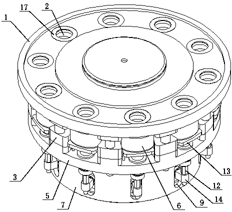
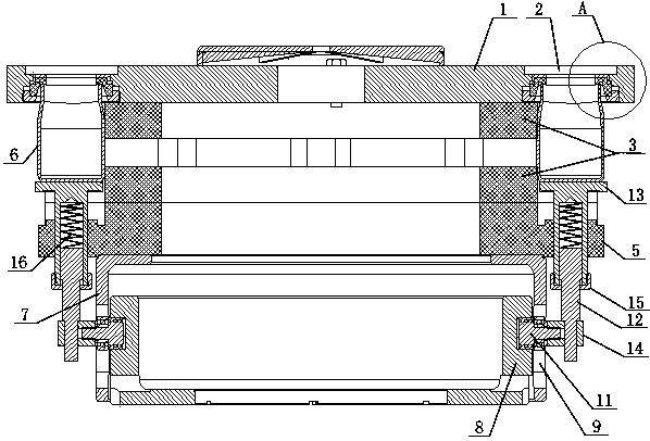
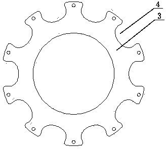
[0019] like Figure 1-4 As shown, a turntable device for a filling machine includes a turntable 1 connected to a rotary drive mechanism and a number of unloading through holes 2 evenly distributed on the turntable 1, and a bottle clamping plate 3 is arranged below the turntable 1 , a number of bottle clamping grooves 4 corresponding to the feeding through holes 2 are arranged around the bottle clamping plate 3, the bottle clamping grooves 4 match the shape of the filling bottle 6, and below the b...


PUM


Abstract

The invention discloses a turntable device for a filling machine. The turntable device comprises a turntable and a plurality of blanking through holes uniformly formed in the turntable, wherein a bottle clamping disk is arranged below the turntable; a plurality of bottle clamping slots corresponding to the blanking through holes are formed in the periphery of the bottle clamping disk and are matched with the shapes of filling bottles; a mandril fixing plate is arranged below the bottle clamping disk; the turntable, the bottle clamping disk and the mandril fixing plate are connected with one another through connection pieces to form a whole; a plurality of bottle jacking mechanisms corresponding to the bottle clamping slots are arranged below the mandril fixing plate; the upper ends of the bottle jacking mechanisms penetrate through the mandril fixing plate to jack up the filling bottles arranged in the bottle clamping slots, so that bottlenecks of the filling bottles can be jacked to the blanking through holes of the turntable. According to the turntable device for the filling machine, the filling bottles are clamped through the bottle clamping disk, so that the filling bottles can completely correspond to the blanking through holes of the turntable one by one and synchronously rotate along with the turntable in the whole filling process; therefore, the filling problem caused by a fact that the filling bottles do not correspond to a blanking hopper in an existing structure can be thoroughly solved.

Description

technical field [0001] The invention relates to a turntable device for a filling machine. Background technique [0002] In the existing filling machine, the filling bottle is conveyed by the conveying mechanism. When the filling bottle is sent to the corresponding blanking station of the turntable, the material is sent to the corresponding filling bottle below by the blanking mechanism to realize filling. Therefore, during the filling process, the precise positioning of the filling bottle is very important. If the bottle mouth does not correspond to the corresponding lower hopper, the material cannot be filled into the filling bottle, thus affecting the normal filling action. . For the conveying of filled bottles, if the filled bottles are of irregular shape, the filled bottles will rotate freely on the conveyor belt due to their mutual extrusion during the conveying process, thus causing the filled bottles to be sent to At the filling station, it is impossible to ensure t...

Claims


Application Information

Patent Timeline
Patent Type & Authority Applications(China)
IPC IPC(8): B67C3/26B67C3/02
Inventor 郑友林
Owner CHENGDU WENJIANG HAIKE INSTR FACTORY
Why Eureka
Try Eureka