A source bottle used in atomic layer deposition equipment

A technology of atomic layer deposition and source bottle, which is applied in the field of source bottle, can solve the problems of not being able to effectively increase the amount of saturated steam in the liquid source, and has no obvious effect, and achieve the effects of improving carrying efficiency, easy implementation, and expanding the contact area

Active Publication Date: 2016-08-17
BEIJING NAURA MICROELECTRONICS EQUIP CO LTD
View PDF3 Cites 2 Cited by
  • Summary
  • Abstract
  • Description
  • Claims
  • Application Information

AI Technical Summary

Problems solved by technology

However, the main effect of this source bottle structure design is to improve the utilization rate of the remaining liquid source, but it cannot effectively increase the amount of saturated steam generated by the liquid source. Diffusion efficiency, did not play a significant role

Method used


Image

  • A source bottle used in atomic layer deposition equipment
  • A source bottle used in atomic layer deposition equipment
  • A source bottle used in atomic layer deposition equipment

Examples


Embodiment 1

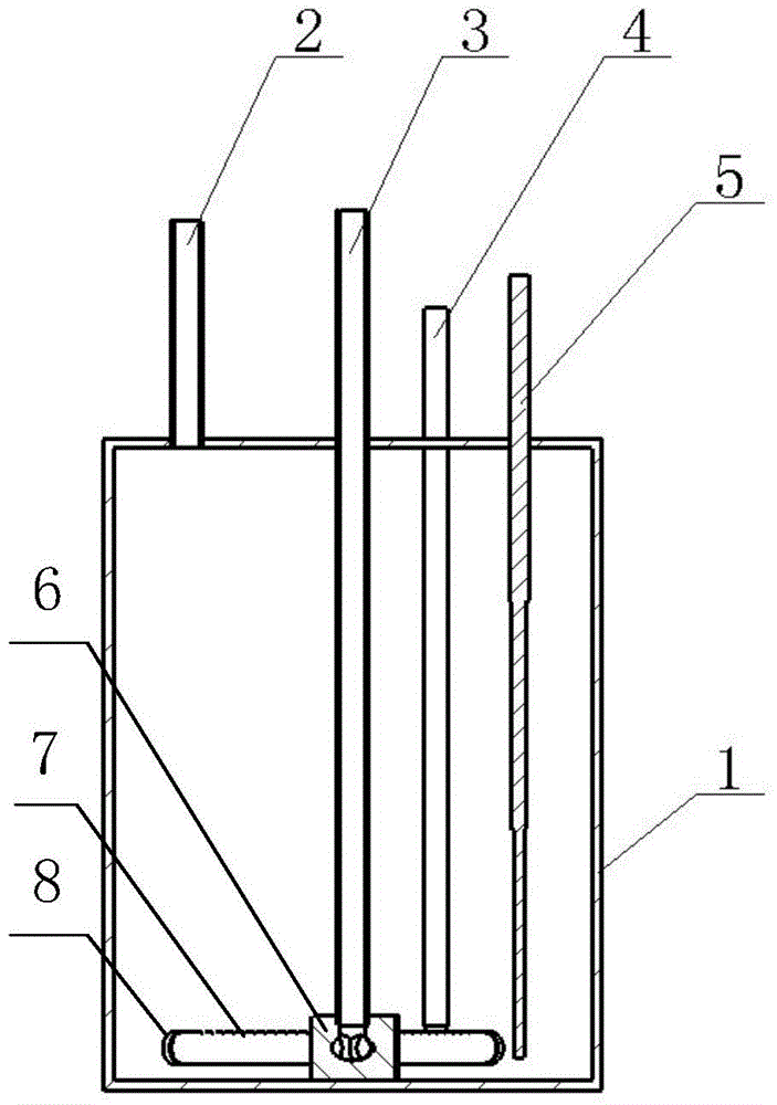
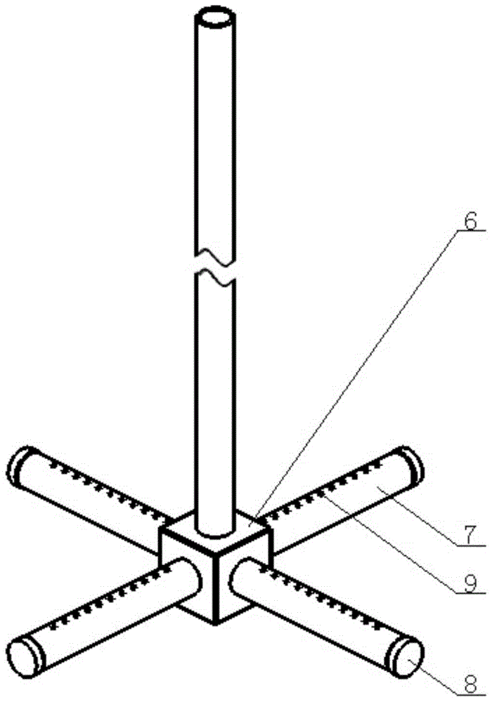
[0027] In this example, see figure 1 , figure 1 It is a schematic diagram of the cross-sectional structure of the source bottle of the present invention. As shown in the figure, the source bottle of the present invention includes a bottle body 1, and the top of the bottle body 1 is provided with an air inlet, an air outlet, a temperature sensor interface and a liquid level sensor interface through the inside and outside. The air inlet pipe 3 extends into the vicinity of the bottom of the bottle body 1 through the air inlet, and is sealed and welded together with the bottle body 1 at the top air inlet of the bottle body 1 . One end of the air inlet pipe 3 located outside the bottle body communicates with the carrier gas source, and the bottom end in the bottle body 1 is sealed and welded to the inlet of the five-way joint 6 . Four equal-length and equal-diameter bubbling tubes 7 with circular cross-sections are distributed horizontally in a cross shape, and one end is sealed ...

Embodiment 2

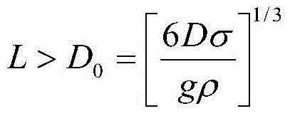
[0040] In the present embodiment, the diameter of the air hole 9 on the bubbler tube 7 is set to be 1.0mm, according to the air hole diameter D and the bubble diameter D 0 The relationship formula between: The bubble diameter can be obtained as 3.54mm (wherein, the density of water at normal temperature (21°C) ρ=1.0×10 3 kg / m 3 , the surface tension coefficient of water at normal temperature (21°C) σ = 7.266N / m, the acceleration of gravity g = 9.8m / s 2 ). Therefore, the hole spacing between the adjacent air holes 9 on the bubbling tube 7 should be greater than 3.54 mm, so it is rounded to 4.0 mm. Other structural settings and conditions in this embodiment are the same as those in Embodiment 1, and will not be expanded here.

[0041] It should be noted that when the bubbles generated by the carrier gas are rising, the liquid source liquid will gradually spread to the inside of the bubbles and gradually reach saturation. Comparative analysis embodiment one and embodiment t...


PUM

PropertyMeasurementUnit
densityaaaaaaaaaa

Abstract

The invention discloses a source bottle applied to atomic layer deposition equipment. A plurality of horizontally arranged bubbling tubes with a plurality of pores are communicated with an intake tube which is inserted to the bottom of the bottle body; all the bubbling tubes are hollow tubes with equal length and equal diameter, the tail ends of the hollow tubes are closed, and the hollow tubes are distributed with the bottom end of the intake tube as the center by equal angles; the pitch of the pores has certain corresponding relationship with the pore diameter. According to the invention, the number of bubbles generated by introducing the carrier gas into the liquid source is sufficiently increased and the contact area of the carrier gas and the liquid source is expanded, so that, the carrying efficiency of the carrier gas is greatly improved; meanwhile the source bottle can be allowed to be applied to the liquid source of lower liquid level; moreover, the invalid loss of the liquid source is reduced and the liquid source resource is saved.

Description

technical field [0001] The present invention relates to a source bottle used in atomic layer deposition equipment, and more particularly, to a source bottle inlet tube bubbling device that can improve the carrying efficiency of liquid source. Background technique [0002] Atomic Layer Deposition (ALD), first known as Atomic Layer Epitaxy (ALE), is a semiconductor film preparation technology proposed by Finnish scholar Tuomo Suntola. [0003] The main reaction method of the atomic layer deposition technology is: at a certain temperature, the first reaction precursor is introduced into the reaction chamber of the atomic layer deposition equipment, so that the precursor molecules are adsorbed on the surface of the substrate to form an active agent; When the adsorption of the substance reaches a saturated state, the first precursor and by-products are removed; then, the second reaction precursor is introduced, and the second precursor and the active agent that has been adsorbed ...

Claims


Application Information

Patent Timeline
Patent Type & Authority Patents(China)
IPC IPC(8): C23C16/455
Inventor 苏艳波兰云峰任鑫
Owner BEIJING NAURA MICROELECTRONICS EQUIP CO LTD
Why Eureka
Try Eureka