An evaporator flow path

A technology of an evaporator and a first flow path, applied in the direction of evaporator/condenser, refrigeration components, refrigerators, etc., can solve the problems of increased process requirements for air conditioning, inconsistent heat exchange length, low cooling effect, etc., and achieves excellent craftsmanship. , Wide range of safety, the effect of not easy to drift

Active Publication Date: 2016-03-23
GUANGDONG CHIGO AIR CONDITIONING
View PDF5 Cites 0 Cited by
  • Summary
  • Abstract
  • Description
  • Claims
  • Application Information

AI Technical Summary

Problems solved by technology

[0009] Due to the heat transfer efficiency of the evaporator, the lower half of the heat transfer is poor, that is, the heat transfer performance of the lower left branch is poor, and this design can only ensure that the number of U-shaped tubes with good heat transfer performance is 11, and the cooling capacity is low , so the cooling effect is low. At the same time, the heat exchange lengths of the first flow path and the second flow path are inconsistent, and the requirements for the production process of the air conditioner are increased.

Method used


Image

  • An evaporator flow path
  • An evaporator flow path
  • An evaporator flow path

Examples


Embodiment 1

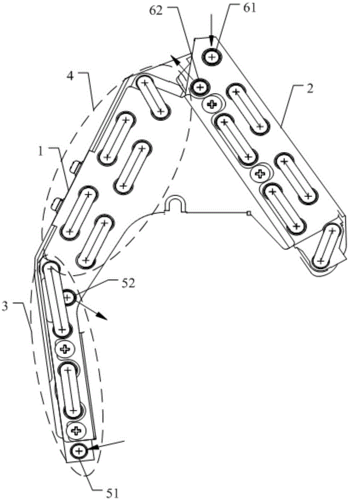
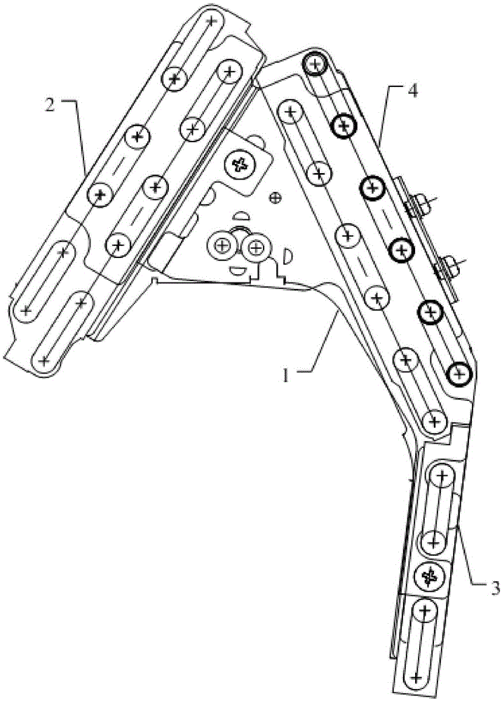
[0031] An evaporator flow path provided in this embodiment includes an evaporator, a first flow path, and a second flow path. The evaporator includes a left branch and a right branch 2, and the left branch is set as a single row of pipes. The lower left branch 3 is composed of the upper left branch 4 configured as a double row of pipes, the lower left branch 3, the upper left branch 4 and the right branch 2 configured as a double row of pipes are connected in sequence,

[0032] The first flow path includes the first liquid inlet pipe 51, the row pipe of the lower left branch 3, the cross pipe 7, the row pipe of the upper left branch 4 and the first liquid outlet pipe 52 connected in sequence, and the cross pipe 7 Connected to the row pipe at the upper end of the left lower branch 3 and the row pipe at the upper end of the left upper branch 4;

[0033] The second flow path includes a second liquid inlet pipe 61 , a drain pipe of the right branch 2 , a drain pipe of the upper le...

Embodiment 2

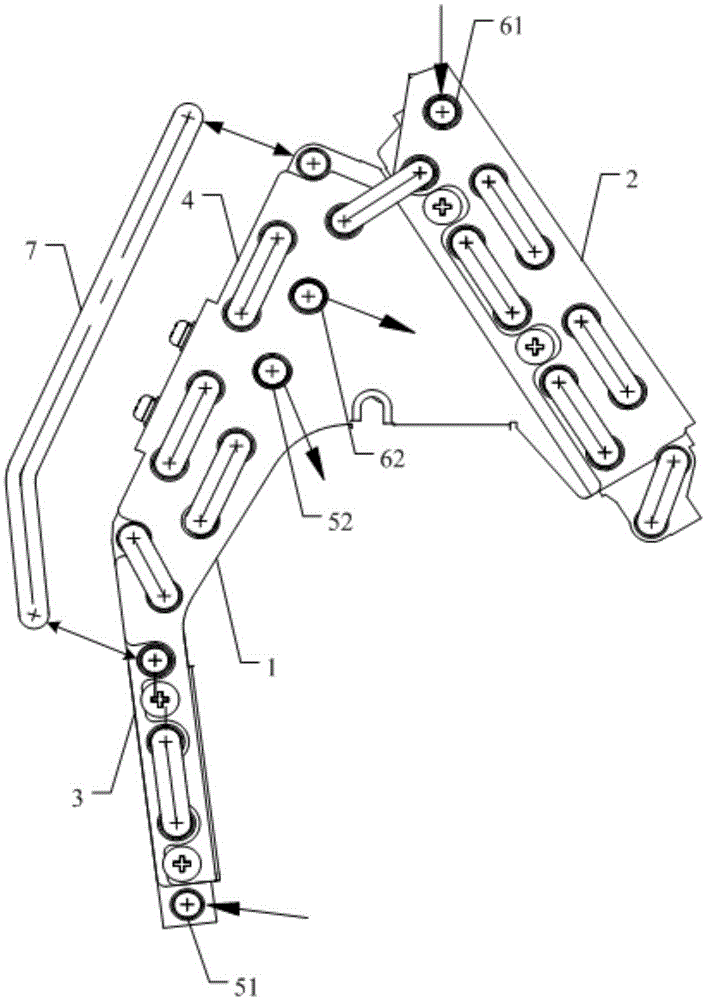
[0040] An evaporator flow path provided in this embodiment includes an evaporator, a first flow path, and a second flow path. The evaporator includes a left branch 1 and a right branch 2, and the left branch 1 is configured as a single The lower left branch 3 of the row of pipes is composed of the upper left branch 4 configured as a double row of pipes, the lower left branch 3, the upper left branch 4 and the right branch 2 configured as a double row of pipes are connected in sequence,

[0041] The first flow path includes the first liquid inlet pipe 51, the row pipe of the lower left branch 3, the cross pipe 7, the row pipe of the upper left branch 4 and the first liquid outlet pipe 52 connected in sequence, and the cross pipe 7 Connected to the row pipe at the upper end of the left lower branch 3 and the row pipe at the upper end of the left upper branch 4;

[0042] The second flow path includes a second liquid inlet pipe 61 , a drain pipe of the right branch 2 , a drain pip...


PUM


Abstract

The invention provides flow paths of an evaporator. The heat exchange lengths and the heat exchange effects of the flow paths are basically the same, it is guaranteed that the heat exchange effects of branches are basically the same, manufacturability is good, and an air conditioner provided with the evaporator can reach high heat exchange efficiency under various working conditions. The flow paths comprise the evaporator, the first flow path and the second flow path. The evaporator comprises the left branch and the right branch, the left branch is composed of a lower left branch and an upper left branch, wherein the lower left branch is arranged into a row of tubes, the upper left branch is arranged into double rows of tubes, and the lower left branch, the upper left branch and the right branch which is arranged into the double rows of tubes are sequentially connected. The first flow path comprises a first liquid inlet tube, discharge tubes and straddle tubes of the lower left branch, discharge tubes of the upper left branch and a first liquid outlet tube, wherein the first liquid inlet tube, the discharge tubes and the straddle tubes of the lower left branch, the discharge tubes of the upper left branch and the first liquid outlet tube are sequentially connected. The straddle tubes are connected to the discharge tubes at the upper end of the lower left branch and the discharge tubes at the upper end of the upper left branch. The second flow path comprises a second liquid inlet pipe, discharge tubes of the right branch, discharge tubes of the upper left branch and a second liquid outlet tube, wherein the second liquid inlet pipe, the discharge tubes of the right branch, the discharge tubes of the upper left branch and the second liquid outlet tube are sequentially connected.

Description

technical field [0001] The invention relates to the field of air conditioning, in particular to an evaporator flow path. Background technique [0002] The air conditioner can adjust the temperature, humidity and cleanliness of the air in a closed space or area to meet the requirements of human comfort and indoor temperature. With the development of society and the diversification of the use of air conditioners, they are also gradually developing towards refinement. More and more companies are improving air conditioners in the direction of "small and thin". [0003] After the volume of the air conditioner becomes smaller, the air inlet must be narrowed, but the heat exchange in the upper part of the air outlet is good, but the heat exchange in the lower part is poor. Therefore, in order to cater to this heat exchange characteristic, air conditioner manufacturers are evaporating The lower half of the heat exchange difference of the evaporator is set from a double row of tubes...

Claims


Application Information

Patent Timeline
Patent Type & Authority Patents(China)
IPC IPC(8): F25B39/02
Inventor 唐利刘飞甘代辉高永胜
Owner GUANGDONG CHIGO AIR CONDITIONING
Why Eureka
Try Eureka