Heat exchanger, in particular for an over critical cooling circuit

A technology of heat exchanger and refrigeration cycle, applied in the direction of heat exchange equipment, heat exchanger type, heat exchanger shell, etc., can solve the problems of increasing pressure drop, affecting the effective power of cooling liquid cooler, and air heating, etc. To achieve the effect of reducing pressure drop

Inactive Publication Date: 2007-01-24
BEHR GMBH & CO KG
View PDF5 Cites 4 Cited by
  • Summary
  • Abstract
  • Description
  • Claims
  • Application Information

AI Technical Summary

Problems solved by technology

This construction and arrangement has various disadvantages: On the one hand, the arrangement of the gas cooler before the coolant cooler affects the effective performance of the coolant cooler, since the gas cooler on the one hand increases the pressure drop on the pressure side, On the other hand, it dissipates its own heat into the air passing through it, thus making the air warmer

Method used


Image

  • Heat exchanger, in particular for an over critical cooling circuit
  • Heat exchanger, in particular for an over critical cooling circuit
  • Heat exchanger, in particular for an over critical cooling circuit

Examples


Embodiment Construction

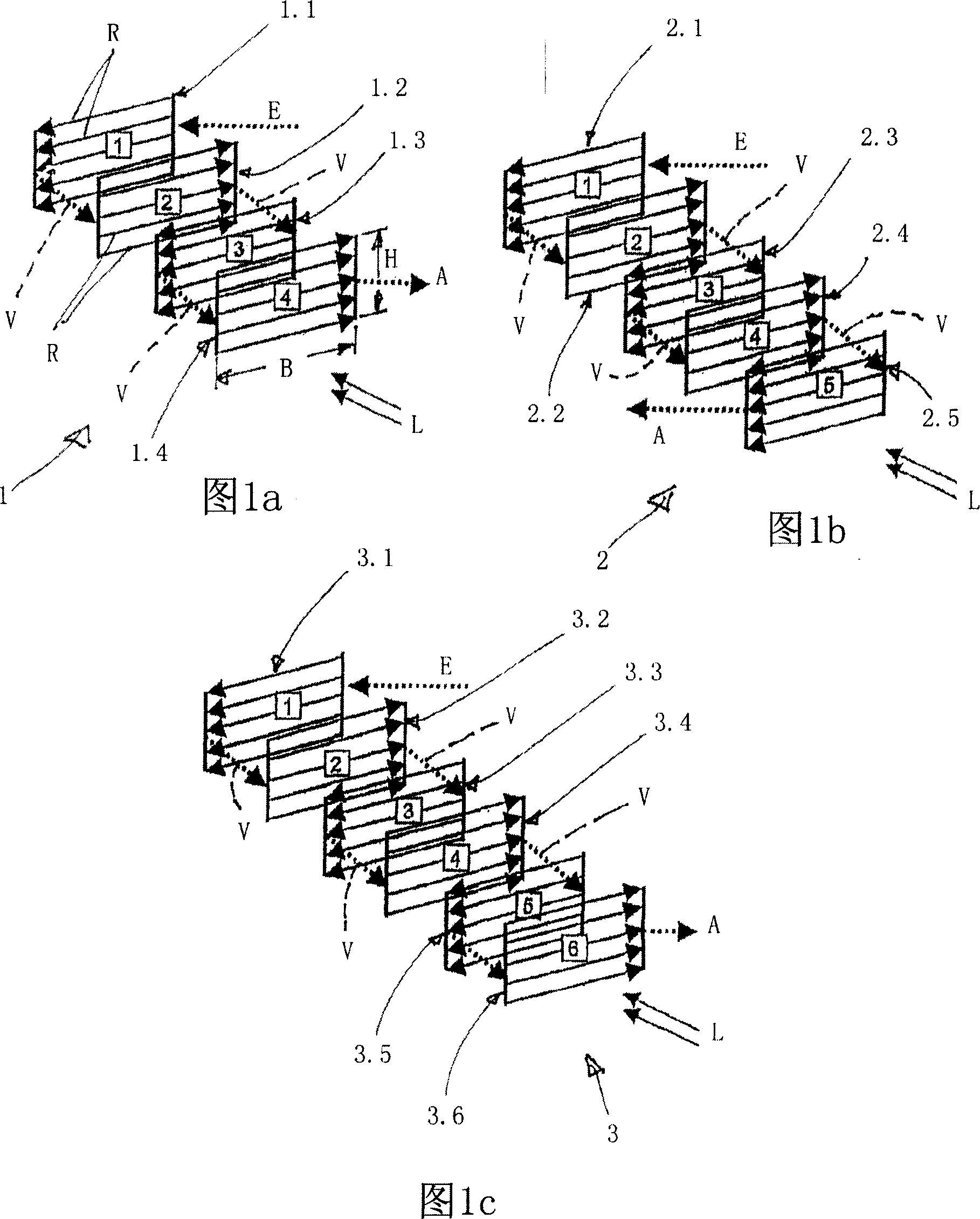
[0032] Figures 1a, 1b and 1c are schematic diagrams of a first embodiment of a heat exchanger according to the invention designed as a gas cooler for a supercritical refrigeration cycle. Such a gas cooler can be used in particular in vehicle air conditioning systems with CO2 (R744) as refrigerant.

[0033] In FIG. 1 a is a four-row pipe system for a gas cooler 1 through which the refrigerant CO2 flows and is cooled by the surrounding air, the flow direction being indicated by the arrow L. In FIG. The gas cooler 1 has four tube rows 1.1, 1.2, 1.3, 1.4 arranged one behind the other in the gas flow direction, each having mutually parallel tubes, which are indicated by arrows R in the figure. Each row of tubes in 1.1 to 1.4 has the same number of tubes, each of which is flowed in parallel. The rows of tubes are connected in series on the refrigerant side, that is to say they are connected to each other by refrigerant connections indicated by dashed arrows V. This connection V is...


PUM


Abstract

The invention relates to a heat exchanger (1), in particular for an over critical cooling circuit. Said heat exchanger comprises a block consisting of tubes (R) and ribs. A gaseous medium, in particular air, can flow over said ribs. A second medium, in particular a coolant, can flow through the tubes (R), which are arranged in at least four rows (1.1, 1.2, 1.3, 1.4), in particular in a cross-counter flow in relation to the gaseous medium.

Description

technical field [0001] The invention relates to a heat exchanger, in particular for a supercritical refrigeration cycle. Background technique [0002] Since the refrigeration process is carried out at a high pressure of up to about 120 bar, the heat exchanger used in the supercritical refrigeration cycle requires that the tubes and collectors have a pressure-resistant structure. Such heat exchangers are known from DE-A 199 06 289, DE-A 100 07 159 and WO 98 / 51983 A. This disclosed heat exchanger is sometimes used as a gas cooler in supercritical refrigeration cycles with CO2 (R744) as the working medium; it is basically characterized by a single-row structure comprising two An array of flattened tubes formed of shaped multi-chambered tubes, the ends of which are secured in headers and sealed eg by brazing. As described in DE-A 100 07 159, the refrigerant flows through the gas cooler in a serpentine manner, that is to say with multiple passes, wherein the refrigerant is defl...

Claims


Application Information

Patent Timeline
IPC IPC(8): F28D1/053F28F9/02
CPCF28F9/0202F28D2021/0073F28D1/0535
Inventor 库尔特·莫尔特格里特·韦尔克
Owner BEHR GMBH & CO KG
Why Eureka
Try Eureka