Exhaust frame

a technology of exhaust frame and exhaust fan, which is applied in the direction of machines/engines, stators, mechanical equipment, etc., can solve the problems of affecting the cooling efficiency of the exhaust frame. , to achieve the effect of reducing the cooling efficiency of the exhaust fram

Active Publication Date: 2019-09-24
MITSUBISHI POWER LTD
View PDF16 Cites 1 Cited by
  • Summary
  • Abstract
  • Description
  • Claims
  • Application Information

AI Technical Summary

Benefits of technology

[0006]The inter-strut space is defined in a tubular shape such as to cover the strut which extends across the combustion gas passage at a position on the downstream side as compared to the cooling air supply hole and the final stage wheel space in the flow direction of the combustion gas. Therefore, as compared to the flow path length in the case of flowing by way of that portion of the inter-strut space which is the nearest to the cooling air supply hole (this portion will hereinafter be referred to as the near-side space), the flow path length in the case of flowing by way of that portion of the inter-strut space which is the farthest from the cooling air supply hole (this portion will hereinafter be referred to as the far-side space) is longer. In general, the pressure loss of cooling air which flows through a passage or flow path is smaller as the flow path length is shorter. In the case where the supply pressure of the cooling air is constant, the flow rate of the cooling air is increased as the pressure loss is reduced. In JP-2005-83199-A, therefore, the flow rate of the cooling air flowing via the near-side space is increased, whereas the flow rate of the cooling air flowing via the far-side space is decreased.
[0007]When the flow rate of the cooling air flowing by way of the far-side space is decreased, the cooling air becomes liable to stagnate in the passage in the vicinity of the inlet of the far-side space. In this case, the cooling efficiency for the exhaust frame may be lowered in the vicinity of the inlet of the far-side space.
[0010]According to the present invention, it is possible to restrain the cooling efficiency for an exhaust frame from being lowered.

Problems solved by technology

When the flow rate of the cooling air flowing by way of the far-side space is decreased, the cooling air becomes liable to stagnate in the passage in the vicinity of the inlet of the far-side space.

Method used


Image

  • Exhaust frame
  • Exhaust frame
  • Exhaust frame

Examples


Embodiment Construction

(Configuration)

1. Gas Turbine

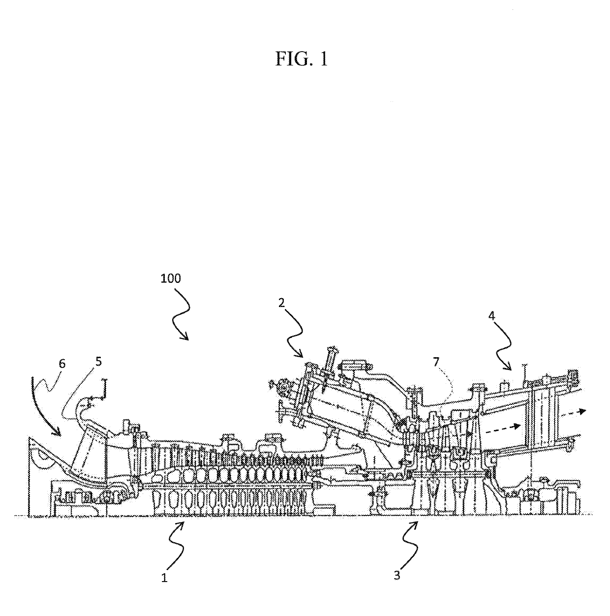
[0019]FIG. 1 illustrates a configuration example of a gas turbine provided with an exhaust frame according to a first embodiment. The exhaust frame according to this embodiment is applied, for example, to a heavy structure type gas turbine that is disposed on the ground and used mainly for power generation.

[0020]As shown in FIG. 1, the gas turbine 100 includes a compressor 1, a combustor 2, a turbine 3 and an exhaust frame 4. In this embodiment, the compressor 1 and the turbine 3 are connected to each other through a shaft (not shown). The compressor 1, which is rotationally driven by the turbine 3, compresses air 6 sucked in through a suction part 5 to generate high-pressure air (combustion air), and supplies the high-pressure air to the combustor 2. The combustor 2 mixes the high-pressure air supplied from the compressor 1 with a fuel supplied from a fuel system (not shown), burns a resultant mixture to generate a high-temperature combustion gas 7, and...


PUM


Abstract

An exhaust frame includes: an inner casing; an inner diffuser which defines, between the inner diffuser and the inner casing, an annular inner cooling passage connected to a final-stage wheel space; an outer diffuser which defines an exhaust passage between the outer diffuser and the inner diffuser; an outer casing which defines an annular outer cooling passage between the outer casing and the outer diffuser; a strut which connects the inner casing and the outer casing to each other while crossing the exhaust passage; a strut cover which connects the inner diffuser and the outer diffuser to each other, and defines, between the strut cover and the strut, an annular connection passage connecting the inner cooling passage and the outer cooling passage to each other; and a communication hole provided in a wall of the outer cooling passage at a position on the downstream side of a center line of the strut in the flow direction of a combustion gas.

Description

BACKGROUND OF THE INVENTION[0001]1. Field of the Invention[0002]The present invention relates to an exhaust frame for a gas turbine.[0003]2. Description of the Related Art[0004]In recent years, for enhancing the efficiency of a gas turbine, there has been a demand for a rising combustion temperature. A rise in the combustion temperature of a gas turbine is accompanied by a rise in the temperature of the exhaust gas from the turbine, and, as a result, the temperature of the exhaust frame into which the exhaust gas flows can also be raised. Therefore, it is necessary to efficiently cool the exhaust frame, for securing maintainability of the exhaust frame.[0005]As a method for cooling the exhaust frame, there is a method in which cooling air supplied into the exhaust frame via a cooling air supply hole is led to a final stage wheel space of the turbine by way of inter-strut spaces each of which is defined between a strut and a strut cover (see, for example, JP-2005-83199-A).SUMMARY OF ...

Claims


Application Information

Patent Timeline
Patent Type & Authority Patents(United States)
IPC IPC(8): F01D25/30F02C7/18F01D9/06F01D25/14F01D25/12F01D25/26
CPCF01D25/12F01D25/14F01D9/065F01D25/26F02C7/18F01D25/30Y02T50/675F05D2260/20F05D2260/941F01D25/24F02C7/00Y02T50/60
Inventor TAKEDA, TAKUYANAKAMURA, TETSUYAKAWAI, RYONANATAKI, KENJI
Owner MITSUBISHI POWER LTD
Why Eureka
Try Eureka