An online turbidity sensor with defoamer

A turbidity sensor and defoamer technology, applied in the field of detection sensors, can solve the problems of large heat generation, long optical path, large sampling amount, etc., and achieve the effect of obvious defoaming effect, high measurement accuracy and low heat generation.

Active Publication Date: 2016-06-15
YANTAI DONGRUN INSTR
View PDF11 Cites 0 Cited by
  • Summary
  • Abstract
  • Description
  • Claims
  • Application Information

AI Technical Summary

Problems solved by technology

[0009] 1. The volume of the flow path is large, the sampling volume is large, the flow path is short, the defoaming effect is not obvious, and the effect of equilibrium temperature difference is not obvious
[0010] 2. The detection channel and the sample liquid are not isolated or only partially isolated, which leads to the improvement of the sealing and anti-corrosion requirements of the detection channel, and the dirt and aerosol on the sealing surface have adverse effects on the test results
The large volume leads to a long optical path, which requires the use of high-power emitting lamps, which leads to large heat generation, temperature difference and heat dissipation problems, and higher requirements on the power supply circuit of the emitting lamps.
Replacing the emitter lamp and cleaning maintenance operations are complex

Method used


Image

  • An online turbidity sensor with defoamer
  • An online turbidity sensor with defoamer
  • An online turbidity sensor with defoamer

Examples


Embodiment Construction

[0033] The principles and features of the present invention are described below in conjunction with the accompanying drawings, and the examples given are only used to explain the invention, not to limit the scope of the invention.

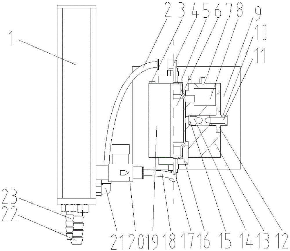
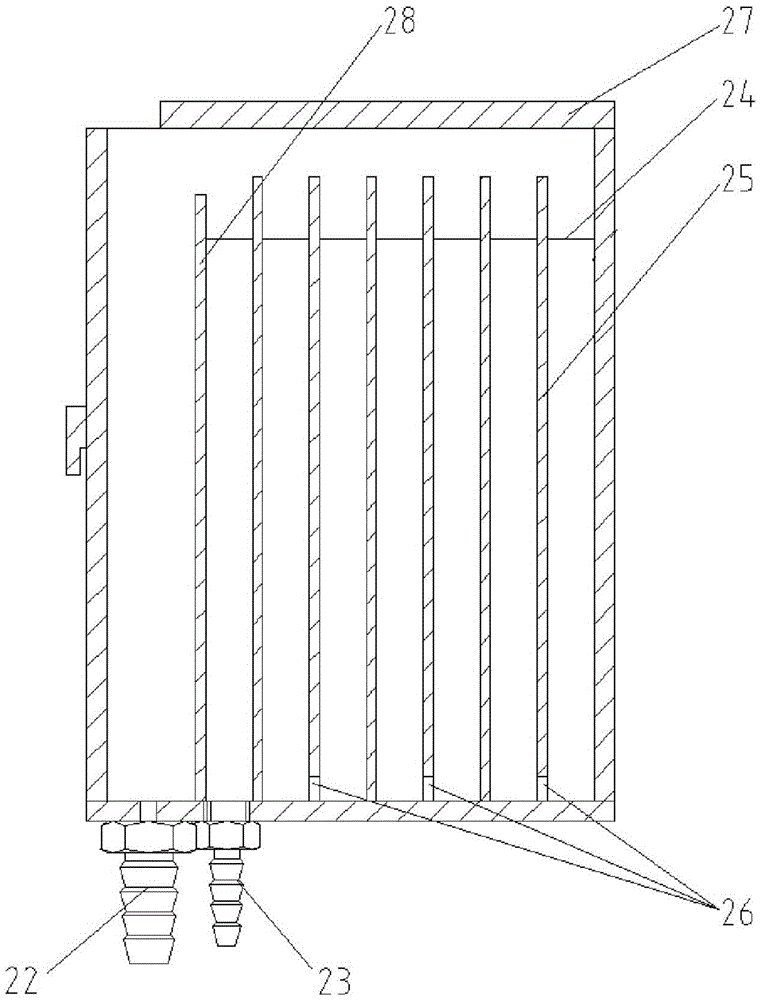
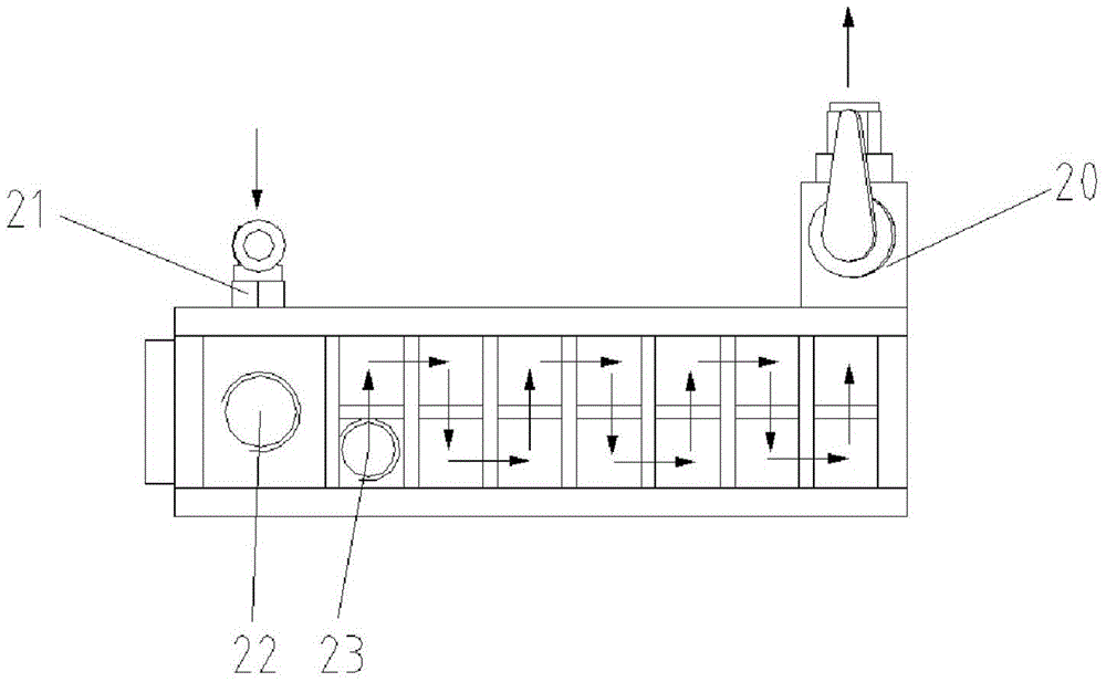
[0034] Such as figure 1 , figure 2 , Figure 4 and Figure 5 As shown, an online turbidity sensor with a defoamer includes a defoamer 1, a sensor, and a mounting plate 9 arranged vertically, and the defoamer 1 includes a shell with an open top and an inner cavity surrounded by the shell , the edge of one side of the bottom of the shell is fixedly provided with a liquid discharge joint 22 connected to the inner cavity, and at the bottom of the shell close to the liquid discharge joint 22 and away from the bottom edge of the shell is fixedly provided with a liquid inlet joint 23 connected with the inner cavity. A front liquid baffle 28 is vertically integrally formed between the bottom, the liquid discharge joint 22 and the liquid inlet joint 23,...


PUM


Abstract

The invention relates to an online turbidity sensor with a defoamer, which comprises a vertically arranged defoamer, a sensor and a mounting plate. The defoamer includes a shell with an open top and an inner cavity surrounded by the outer shell. The inner cavity There are a front liquid baffle, a liquid baffle and a liquid baffle inside, an opening is opened at the bottom of the liquid baffle, a liquid outlet joint and a liquid return joint connected to the inner cavity are fixedly installed on the vertical side wall of the shell, and a liquid return joint is fixedly installed at the bottom. The liquid inlet joint and the liquid discharge joint connected to the inner cavity; the sensor includes a sampling tube, a housing base whose bottom is fixed vertically on the mounting plate and a housing cover that can be opened and closed on the housing base, the housing base and the housing A sampling tube is arranged between the covers, and an emission lamp, a first detector and a second detector are arranged corresponding to the sampling tube on the base of the housing; Connectors and return connectors. The beneficial effect is that the sampling volume is small, the defoaming effect is obvious, the maintenance is convenient and the structure is compact.

Description

technical field [0001] The invention relates to a detection sensor, in particular to an online turbidity sensor with a defoamer. Background technique [0002] In the field of online flow-through water quality turbidity measurement, the principle of 90° scattering measurement is widely used. The sample liquid flows through the sensor cavity or the channel in the cavity. After the light emitted by the emitter located in the cavity is scattered by the sample liquid, the light intensity detected by the light receiver located in the cavity at 90° to the emitted light is the same as that of the sample. Liquid turbidity has a corresponding relationship. The sensor cavity or the channel in the cavity needs to be cleaned regularly through the built-in cleaning device or disassembled, so the volume is relatively large, resulting in a long optical path. Usually, a high-power emitting lamp is used to ensure the effective light intensity within the measurement range. In order to elimin...

Claims


Application Information

Patent Timeline
Patent Type & Authority Patents(China)
IPC IPC(8): G01N21/17
Inventor 马正于兆慧夏军许晓蔡宗岐吕颖张建林周铭华
Owner YANTAI DONGRUN INSTR
Why Eureka
Try Eureka