Device and method for correcting motor rotor shaft

A technology of a motor rotor and a correction device, which is applied to electromechanical devices, manufacturing motor generators, electrical components, etc., can solve the problems of difficult control of the correction value, increased vibration and noise of the complete set of equipment, time-consuming and other problems, and achieves simple and convenient correction. Effect

Active Publication Date: 2016-01-13
NINGBO ANXIN CNC TECH
View PDF7 Cites 0 Cited by
  • Summary
  • Abstract
  • Description
  • Claims
  • Application Information

AI Technical Summary

Problems solved by technology

[0002] In the existing motor production process, the motor rotor is an important process in the motor manufacturing process, especially in the production process of the output shaft of the motor rotor, because the shaft and the rotor core are assembled by cold pressing or heat sleeve, etc. The slight deformation and bending produced by the method cannot meet the design requirements of the radial runout of the output shaft end, so that when the motor product is used, the equipment connected to it will generate vibration and other unstable factors during operation, resulting in increased vibration and noise of the complete set of equipment. Large size, reduced service life and other disadvantages, so the radial runout of the motor rotor shaft must be measured and corrected, but the current common shaft calibration method is to use the final shaft method, that is, to support both ends of the shaft to be calibrated, and then in Pressurization and bending deformation are carried out between the support ends. If the pressure is too high, reverse bending will occur. If the pressure is too small, the correction effect will not be achieved, making it difficult to control the correction value, and it is time-consuming. Even if the axis is corrected According to the requirements, due to the stress on the shaft during cold bending, after the long-term operation of the motor or the action of external forces such as vibration, the original corrected shaft will recover, which brings hidden dangers to the reliability of the motor operation.

Method used


Image

  • Device and method for correcting motor rotor shaft
  • Device and method for correcting motor rotor shaft

Examples


Embodiment Construction

[0017] The present invention will be described in further detail below in conjunction with the embodiments of the drawings.

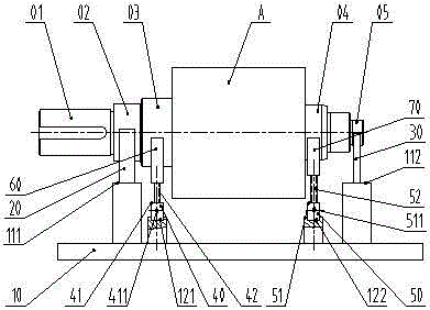
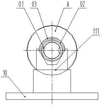
[0018] As shown in the figure, the motor rotor shaft correction device and method, the device includes a chassis 10, a front V-shaped block 20, a rear V-shaped block 30, a front support 40, a rear support 50, a front V-shaped bracket 60, and a rear V-shaped Support 70, the front support 40 includes a front stud 41 and a front screw 42, and the rear support 50 includes a rear stud 51 and a rear screw 52; when the shaft 01 beats, the front bearing block 02 of the motor rotor A rests on the front V block 20, the rear bearing gear 05 rests on the rear V-shaped block 30; when the output shaft is corrected, the front V-shaped bracket 60 is raised to support the front correction section 03, and the rear V-shaped bracket 70 is raised to support the rear correction section 04

[0019] In the above embodiment, the motor rotor output shaft correction device is: the fr...


PUM


Abstract

The invention discloses a motor rotor shaft correction apparatus and method. The apparatus comprises a chassis, a front V-shaped block, a rear V-shaped block, a front support, rear support, a front V-shaped bracket, and a rear V-shaped bracket. For the ease of measurements, a front bearing guard of the motor rotor is placed onto the frontV-shaped block, the rear bearing guard is placed onto the rearV-shaped block, the shaft jitter value and position are measured by using a dial indicator; in order to perform correction on the shaft, the frontV-shaped bracket is lifted to support the front correction section, the rear V-shaped bracket is lifted to support the rear correction section, the front correction section and the rear correction section are knocked through a high-hardness blunt tool to realize the purpose of shaft correction, compared with the prior art, the apparatus and method of the invention has advantages of easy and convenient measurement, adjustment and correction, stability and reliability, and the recovery phenomenon does not occur on the corrected shaft.

Description

Technical field [0001] The invention relates to a radial runout correction device of a motor output shaft, belonging to the technical field of tooling and process methods in motor production. Background technique [0002] In the existing motor production process, the motor rotor is an important process in the motor manufacturing process, especially the output shaft of the motor rotor will be cold pressed or hot sleeved during the assembly process because the shaft and the rotor core are assembled during the production process. The slight deformation and bending produced by the method do not meet the design requirements of the radial runout of the output shaft end, so that when the motor product is used, the connected equipment will generate vibration and other unstable factors during operation, which will increase the vibration and noise of the complete set of equipment. It is necessary to measure and correct the radial runout of the motor rotor’s output shaft, but the current me...

Claims


Application Information

Patent Timeline
Patent Type & Authority Patents(China)
IPC IPC(8): H02K15/00
Inventor 王必生
Owner NINGBO ANXIN CNC TECH
Why Eureka
Try Eureka