Power supply device for controlling light

A technology for a power supply device and a lamp, which is applied to the layout of electric lamp circuits, lighting devices, electric light sources, etc., can solve the problems of inability to control the synchronization of LED lamps, unable to use the light structure of LED lamps, and increased cost.

Inactive Publication Date: 2014-04-09
PHIHONG TECH CO LTD
View PDF4 Cites 5 Cited by
  • Summary
  • Abstract
  • Description
  • Claims
  • Application Information

AI Technical Summary

Problems solved by technology

However, this method needs to set up one or more computers for management, resulting in a substantial increase in cost
[0004]Although LED lamps can be used in traditional fluorescent lamp sockets, they cannot control the state of LEDs through wireless communication, such as the on and off status of LEDs , the illuminance of LEDs and the power consumption of LEDs and other parameters, it is also impossible to control the synchronization of many LED lamps in a specific group through network communication, and it is also impossible to use the light structure of LED lamps for visible light network communication

Method used


Image

  • Power supply device for controlling light
  • Power supply device for controlling light
  • Power supply device for controlling light

Examples


Embodiment Construction

[0023] The present invention will be described in detail below in combination with embodiments and accompanying drawings. It should be understood that all the embodiments in the present invention are used for illustration only, not for limitation. Therefore, in addition to the embodiments herein, the present invention can also be widely applied in other embodiments. And the present invention is not limited to any embodiment, but should be determined by the claims and their equivalent fields.

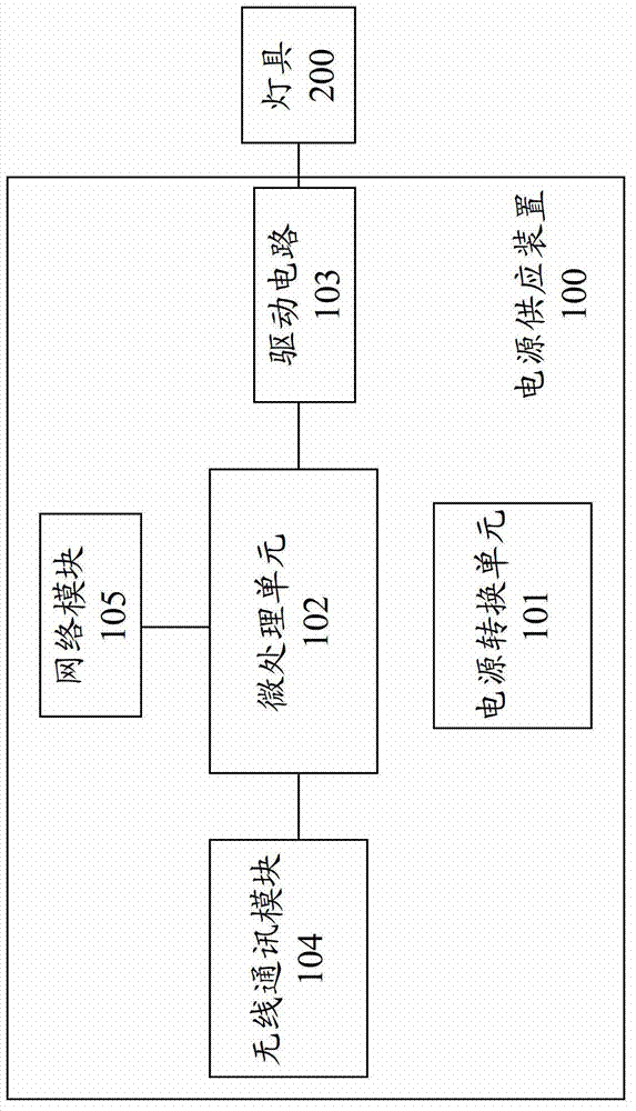
[0024] refer to figure 1 , which is a functional block diagram of the power supply device for supplying power and controlling lamps of the present invention. The power supply device 100 includes a power conversion unit 101 , a micro-processing unit 102 , a driving circuit 103 , a wireless communication module 104 and a network module 105 . The power supply device 100 is used to provide power to the lamp 200 , and the power supply device 100 can control the lamp 200 . The power conver...


PUM


Abstract

The invention provides a power supply device for controlling a light. The power supply device comprises a micro-processing unit, a power converting unit coupled to the micro-processing unit to convert ac into dc, a wireless communication module coupled to the micro-processing unit to receive and transmit wireless signals, a network module coupled to the micro-processing unit and a driving circuit coupled to the micro-processing unit to drive the a lighting component in the light.

Description

technical field [0001] The invention relates to a device for controlling a lamp, in particular to a power supply device for supplying power and controlling a lamp. Background technique [0002] In recent years, many countries have made energy conservation and carbon reduction one of their main policies. Of all electrical energy applications, lighting consumes a large portion of electricity. Therefore, if the electricity used for lighting can be reduced, a considerable amount of electricity can be saved, and heat energy and carbon dioxide emissions can be reduced. [0003] There are two common ways to control the lighting system to achieve energy saving. The first is through sensors, such as light sensors or biosensors (infrared sensors, ultrasonic sensors, etc.). The light sensor can sense the intensity of sunlight, so that the system can switch the light on and off, but it is only suitable for outdoors, windows and other areas that can be exposed to sunlight. The biosen...

Claims


Application Information

Patent Timeline
Patent Type & Authority Applications(China)
IPC IPC(8): H05B37/02
Inventor 吴威震
Owner PHIHONG TECH CO LTD
Why Eureka
Try Eureka