Side channel blower having a plurality of feed channels distributed over the circumference

A technology of conveying channels and blowers, which is applied to the components of pumping devices for elastic fluids, mechanical equipment, machines/engines, etc., can solve problems such as high cost and limited degree of freedom, and achieve low manufacturing cost and space saving Effect

Active Publication Date: 2014-04-09
PIERBURG GMBH & CO KG NEUSS
View PDF5 Cites 3 Cited by
  • Summary
  • Abstract
  • Description
  • Claims
  • Application Information

AI Technical Summary

Problems solved by technology

However, the degrees of freedom in this respect are limited, and such adjustments are also associated with high cost tooling and development

Method used


Image

  • Side channel blower having a plurality of feed channels distributed over the circumference
  • Side channel blower having a plurality of feed channels distributed over the circumference
  • Side channel blower having a plurality of feed channels distributed over the circumference

Examples


Embodiment Construction

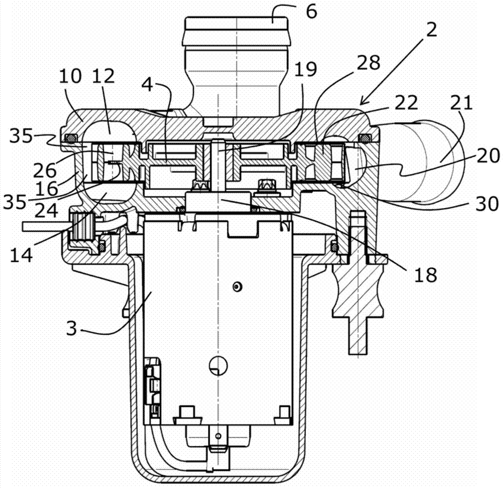
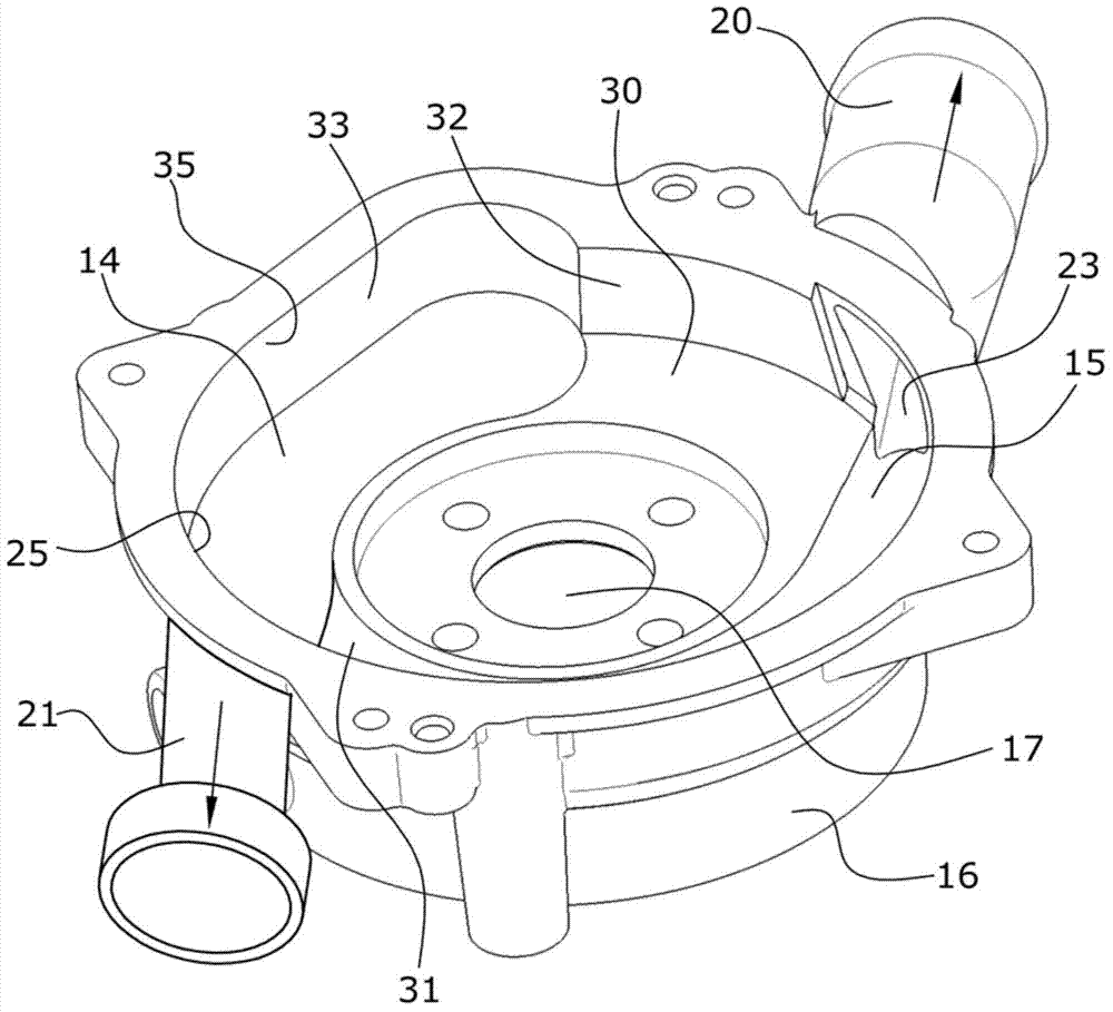
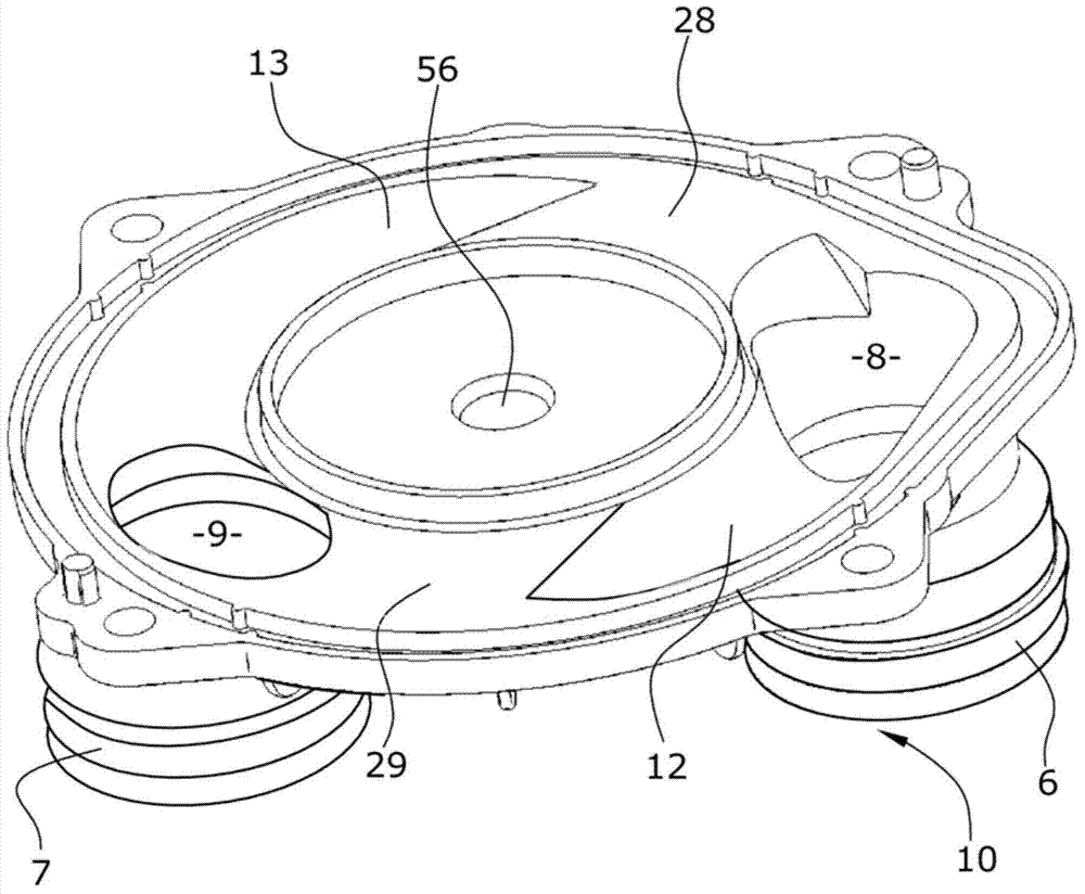
[0017] The embodiment of the blower with side channels shown in the figure is a so-called double helix design, in which not only in the first but also in the second housing part, there are two conveying channels which follow each other in the circumferential direction, here Conveyor channels extending axially parallel to one another each have an outlet region, which merge into a common outlet. figure 1 The section in is chosen to extend through a delivery channel. exist figure 1 The blower with side channel shown in , consists of a housing 2 divided into two parts and an impeller 4 which is rotatably mounted in the housing 2 and which can be driven by a drive unit 3 , for example for conveying air. The air passes through the axial inlet 6 into the inlet region 8 of the first housing part 10 which in this embodiment serves as a cover for a blower with side channels. From the outlet area 8, the air then flows into two substantially arc-shaped delivery channels 12, 14, wherein ...


PUM


Abstract

The invention relates to a side channel blower, in particular a secondary air pump for an internal combustion engine, comprising a multi-part housing which has at least one inlet (6, 7) and at least one outlet (20, 21) and has substantially one first and one second housing part (10, 16), wherein the inlet (6, 7) and the outlet (20, 21) are fluidically connected via at least one inlet region (8, 9), extending over at least one at least partially annular feed channel (12, 14) formed in the first and/or second housing part (10, 16) and via at least one outlet region (23, 25), comprising an impeller (4) which is rotatably mounted in the housing (2) and can be driven via a drive unit (3), wherein the impeller (4) has conveying blades (22) which interact with the opposite feed channel and comprising at least one interruption region (28, 30) between the inlet region (8); and in the outlet region (23, 25), in which the at least one feed channel (12, 14) is interrupted in the circumferential direction, wherein there is at least one feed channel (12, 14) which has a circumferential angle of 300 DEG.

Description

technical field [0001] The invention relates to a side channel blower, in particular a secondary air pump for an internal combustion engine, comprising a multi-part housing having at least one inlet and at least one outlet and generally a first and a second The housing part, wherein the inlet is fluidically connected to the outlet via at least one inlet area, via at least one delivery channel designed in an at least partially annular extension in the first and / or second housing part, and via at least one outlet area, Consists of an impeller, which is rotatably mounted in the housing and can be driven by a drive unit, wherein the impeller has conveying blades, which cooperate with the opposite conveying channel, and at least one between the inlet area and the outlet area A discontinuity in which at least one conveying channel is cut off in the circumferential direction. Background technique [0002] Such blowers or pumps with side channels are known and described in numerous...

Claims


Application Information

Patent Timeline
Patent Type & Authority Applications(China)
IPC IPC(8): F04D23/00
CPCF04D23/008F04D13/06F04D29/281
Inventor H.帕弗拉思
Owner PIERBURG GMBH & CO KG NEUSS
Why Eureka
Try Eureka