Power generation system and control method thereof

A power generation system, Tesla turbine technology, applied in engine components, machines/engines, steam engine devices, etc., can solve the problem that the efficiency of gas-steam combined cycle power generation system cannot be further improved, and achieve the effect of improving efficiency

Pending Publication Date: 2018-11-23
刘慕华
View PDF0 Cites 0 Cited by
  • Summary
  • Abstract
  • Description
  • Claims
  • Application Information

AI Technical Summary

Problems solved by technology

[0004] The invention provides a power generation system and its control method to solve the problem that the efficiency of the existing gas-steam combined cycle power generation system cannot be further improved due to the limitation of the steam turbine

Method used


Image

  • Power generation system and control method thereof
  • Power generation system and control method thereof
  • Power generation system and control method thereof

Examples


Embodiment 1

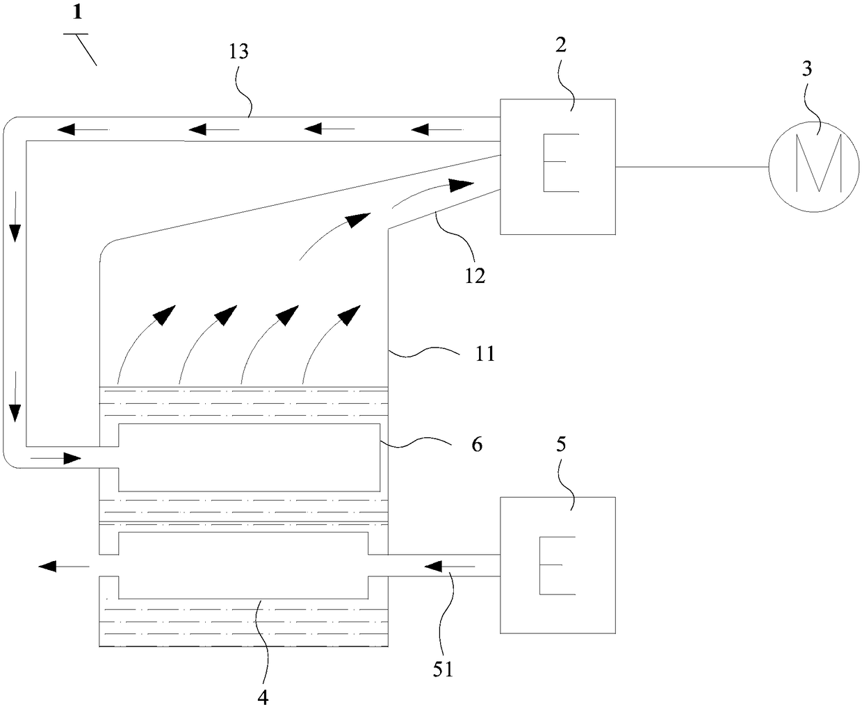
[0098] Such as Figure 1 to Figure 2 As shown, a power generation system includes:

[0099] Waste heat boiler 1, Tesla turbine 2 and motor 3;

[0100] The Tesla turbine 2 is connected to the motor 3, and the Tesla turbine 2 is used to drive the motor 3 to work;

[0101] The Tesla turbine 2 is provided with a medium inlet and a medium outlet;

[0102] The waste heat boiler 1 includes a shell 11, which is filled with a liquid medium, and at least one heat exchanger for converting the liquid medium into a vapor medium is arranged inside the shell 11, and the heat exchanger is immersed in the liquid medium; The casing 11 is provided with a steam pipeline 12 communicating with the medium inlet, and a condensation pipeline 13 communicating with the medium outlet;

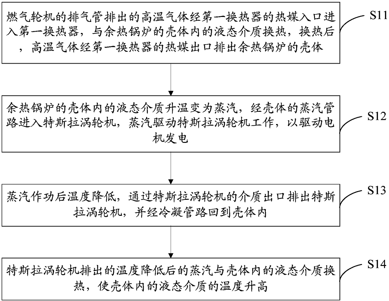
[0103] The heat exchanger includes a first heat exchanger 4 , the heat medium inlet of the first heat exchanger 4 communicates with the exhaust pipe 51 of the gas turbine 5 , and the heat medium outlet of the first hea...

Embodiment 2

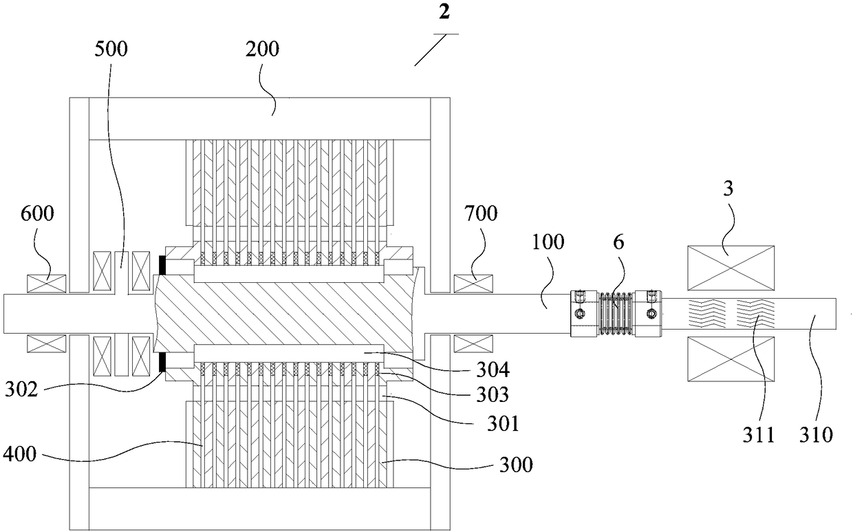
[0124] Such as image 3 As shown, a Tesla turbine 2 comprising:

[0125] Shaft 100;

[0126] A housing 200 disposed on the rotating shaft 100, the housing 200 is provided with a medium inlet (not shown in the figure) and a medium outlet (not shown in the figure);

[0127] Several disks 300 are arranged in the housing 200, and several disks 300 are fixedly connected to the rotating shaft 100. A gap 400 is provided between every two adjacent disks 300 among the several disks 300. Each of the disks 300 is provided with at least one exhaust hole 301;

[0128] And, the thrust bearing 500 and at least two radial bearings disposed on the rotating shaft 100 are non-contact bearings.

[0129] In the embodiment of the present invention, the working principle of the Tesla turbine is as follows: the high-speed fluid medium enters the interior of the housing 200 through the medium inlet provided on the housing 200, and the fluid medium enters the gap between adjacent discs 300 through t...

Embodiment 3

[0186] Such as Figure 6 to Figure 9 As shown, the tubular heat exchanger consists of:

[0187] The first pipe body 10, the second pipe body 20 and the heat exchange element 30, the outer diameter of the first pipe body 10 is smaller than the inner diameter of the second pipe body 20, and the second pipe body 20 is sleeved outside the first pipe body 10;

[0188] A plurality of heat exchange elements 30 are attached and connected between the inner wall of the first pipe body 10 and the outer wall of the first pipe body 10 and the inner wall of the second pipe body 20 , and any two adjacent heat exchange elements 30 There are gaps between them;

[0189] The space between the outer tube wall of the first tube body 10 and the tube inner wall of the second tube body 20 forms a refrigerant channel, and the space surrounded by the first tube body 10 forms a heat medium channel.

[0190] When the tubular heat exchanger of the embodiment of the present invention is applied to a powe...


PUM


Abstract

The invention provides a power generation system and a control method thereof. The power generation system comprises a waste heat boiler, a Tesla turbine and a motor, wherein the Tesla engine is connected with the motor, the Tesla turbine is used for driving the motor to work, and the Tesla turbine is provided with a medium inlet and a medium outlet; the waste heat boiler comprises a shell body, aliquid medium is filled in the shell body, at least one heat exchanger used for converting the liquid medium into a vapor state medium is further arranged inside the shell body, and the heat exchanger is immersed in the liquid medium; and a steam pipeline and a condensation pipeline are arranged on the shell body, wherein the steam pipeline communicating with the medium inlet is arranged on the shell body, and the condensation pipeline communicates with the medium outlet; and the at least one heat exchanger comprises a first heat exchanger, a heat medium inlet of the first heat exchanger communicates with an exhaust pipe of a gas turbine, and the heat medium outlet of the first heat exchanger is located outside the shell body. According to the system and the method, the high-efficiency Tesla turbine is used as a steam turbine, so that the efficiency of the fuel gas and steam combined cycle power generation system is improved.

Description

technical field [0001] The invention relates to the technical field of power generation, in particular to a power generation system and a control method thereof. Background technique [0002] The efficiency of the gas-steam combined cycle power generation system is related to the efficiency of the gas cycle (i.e. the efficiency of the gas turbine) and the efficiency of the steam cycle (i.e. the efficiency of the steam turbine). Improving the efficiency of the gas cycle or the efficiency of the steam cycle can improve the efficiency of the gas-steam combined cycle power generation system . Among them, the improvement of steam cycle efficiency is mainly achieved by increasing the inlet steam parameters of the steam turbine. In the prior art, the steam turbine is usually a steam turbine, and since the steam turbine has high requirements on the quality and parameters of the steam, it also has high requirements on the parameters of the inlet flue gas of the waste heat boiler. I...

Claims


Application Information

Patent Timeline
Patent Type & Authority Applications(China)
IPC IPC(8): F01D25/16F01K13/00F16C32/04F16C32/06F16C41/00
CPCF01D25/166F01K13/00F16C32/04F16C32/06F16C41/00
Inventor 靳普
Owner 刘慕华
Why Eureka
Try Eureka