Turbine vane provided with a recess for embrittlement of a frangible section

a technology of frangible section and turbine, which is applied in the manufacture of engines, mechanical equipment, machines/engines, etc., can solve the problems of limiting the increase in maximum stress harmful for fatigue lifetime, releasing very high-energy debris which cannot be contained by the engine armour, and causing the turbine to find itself in an overspeed scenario

Pending Publication Date: 2022-07-28
SAFRAN HELICOPTER ENGINES
View PDF4 Cites 0 Cited by
  • Summary
  • Abstract
  • Description
  • Claims
  • Application Information

AI Technical Summary

Benefits of technology

[0018]In the light of the above, the invention aims to propose a turbine vane provided with a frangible section for setting the vane breakage speed value without increasing the maximum stress in the vane.
[0021]This recess thus helps embrittle the frangible section of the stilt by increasing the mean stress exerted in the neck of the stilt, without significantly increasing the maximum stress induced locally under the action of thermomechanical forces. It hence helps optimise the setting of the limit speed from which the vanes break.

Problems solved by technology

In the event of breakage of the power transmission line, for example in the event of breakage of the shafting or the transmission line connected to the reduction gear, the turbine can find itself in an overspeed scenario due to the disappearance of the resistive torque applied on the turbine vanes.
This overspeed scenario can be particularly hazardous, result in the breakage of at least one rotary disk supporting the vanes of a stage of the turbine, under the effect of centrifugal force, and trigger the release of very high-energy debris which cannot be contained by the armour provided on the engine.
It has been observed that this maximum stress determines the fatigue lifetime of the vane such that producing this concave zone in the leading edge to embrittle the vane locally requires relatively complex design work in order to define the threshold value from which the stilts break while limiting the increase in maximum stress harmful for the fatigue lifetime of the vane.
Producing a concave zone of increased size in the leading edge of the vane so as to reduce the cross-section of the vane stilt locally would not make it possible to reduce the breakage limit speed of the stilt without increasing the maximum stress on the minimum cross-section on the stilt in a redhibitory way and hence reducing the fatigue lifetime of the vane.

Method used


Image

  • Turbine vane provided with a recess for embrittlement of a frangible section
  • Turbine vane provided with a recess for embrittlement of a frangible section
  • Turbine vane provided with a recess for embrittlement of a frangible section

Examples


Embodiment Construction

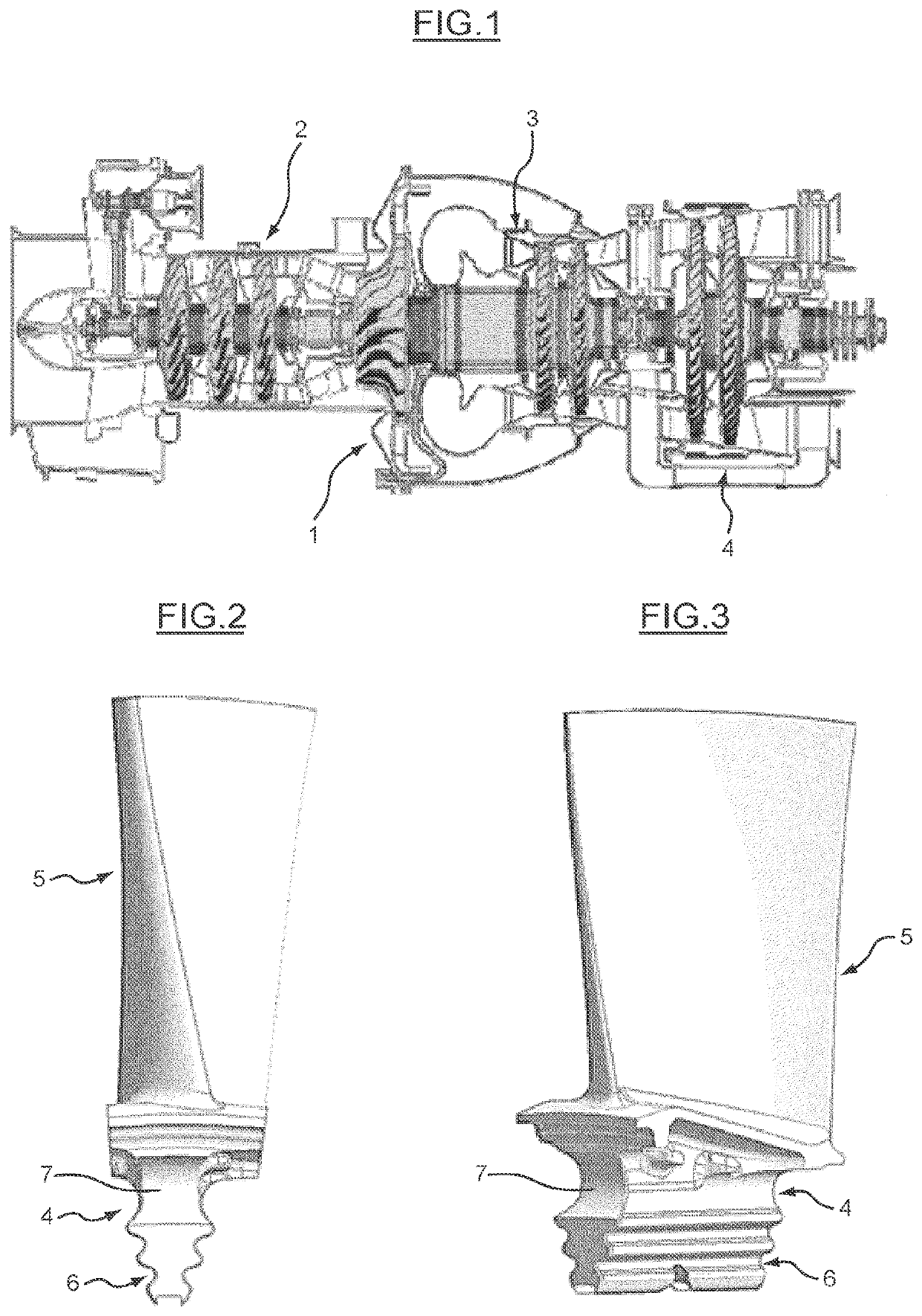
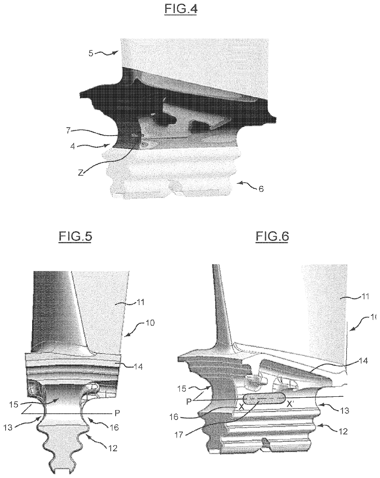
[0043]In FIGS. 5 and 6, a turbine engine vane, in particular a free turbine vane, represented by the general reference number 10, is shown.

[0044]This vane 10 includes a blade 11, a fir-tree root 12 intended to fasten the vane onto a rotor risk, by engaging the root 12 into a housing also known as “receptacle” of corresponding shape formed in the disk, a stilt 13 extending the fir-tree root 12 and a platform 14.

[0045]The fir-tree root extends along a longitudinal axis, which in a manner known per se can form an angle with the axis of rotation A-A′ of the turbine disk, in order to increase the contact length between the fir-tree root and the disk. The axis of the fir-tree root once the vane is mounted on the disk extends along the direction of the corresponding receptacle in the disk. The receptacles of a free turbine disk can be provided each more or less sloping in a tangential plane to the disk, with respect to the axial direction of the disk. In other words, an angle in a tangenti...


PUM


Abstract

A turbine vane of a turbine engine is described. The turbine vane includes a blade and a root. The root includes a stilt having lateral flanks with a curvilinear profile. The stilt includes a frangible zone suitable for undergoing a breakage of the stilt if radial forces higher than a threshold are exerted on the vane, in particular centrifugal forces during an overspeed state of the turbine. The frangible zone includes at least one oblong frangibility recess formed on at least one of the lateral flanks of the stilt, the oblong recess extending in an axial direction of the stilt along a longitudinal axis parallel to or included in a minimum cross-sectional plane which contains a minimum cross-section of the stilt.

Description

TECHNICAL FIELD OF THE INVENTION[0001]The present invention relates to turbine vanes of a turbine engine and, in particular, a turbine vane stilt arrangement. The stilt of a vane is a part supporting the vane blade which extends radially between a lower attachment part known as a “fir-tree root” and a vane platform.[0002]More particularly, the invention relates to turbine vanes of a free-turbine turbine engine.[0003]The invention also relates to a turbine engine comprising such vanes.PRIOR ART[0004]Conventionally, as illustrated in FIG. 1, a free-turbine turbine engine includes a gas generator 1, comprising at least one compressor which includes one or more compression stages 2, a combustion chamber 3, and a turbine wherein the pressurised hot gases from the combustion chamber expand and wherein the kinetic and thermal energy of the gases is converted into mechanical energy to rotate a shaft which connects the turbine to the compressor, so as to also actuate the compressor. A turbin...

Claims


Application Information

Patent Timeline
Patent Type & Authority Applications(United States)
IPC IPC(8): F01D5/30F01D21/02
CPCF01D5/3007F01D21/045F01D21/02F05D2250/294F05D2220/321F05D2260/941F01D5/147F05D2250/712F05D2270/021
Inventor DENAUX, MATTHIEU CLAUDE JEAN
Owner SAFRAN HELICOPTER ENGINES
Why Eureka
Try Eureka