Thermoelectric conversion element and thermoelectric conversion method

A technology of thermoelectric conversion and components, applied in the direction of electrical components, thermoelectric devices, circuits, etc., can solve problems such as inability to convert

Inactive Publication Date: 2014-04-09
NEC CORP +1
View PDF6 Cites 7 Cited by
  • Summary
  • Abstract
  • Description
  • Claims
  • Application Information

AI Technical Summary

Problems solved by technology

Therefore, conventional thermoelectric conversion elements based on thermocouples cannot simultaneously convert the temperature gradient along the direction perpendicular to the plane and the temperature gradient along the in-plane direction of the heat source into electrical energy

Method used


Image

  • Thermoelectric conversion element and thermoelectric conversion method
  • Thermoelectric conversion element and thermoelectric conversion method
  • Thermoelectric conversion element and thermoelectric conversion method

Examples


example 1

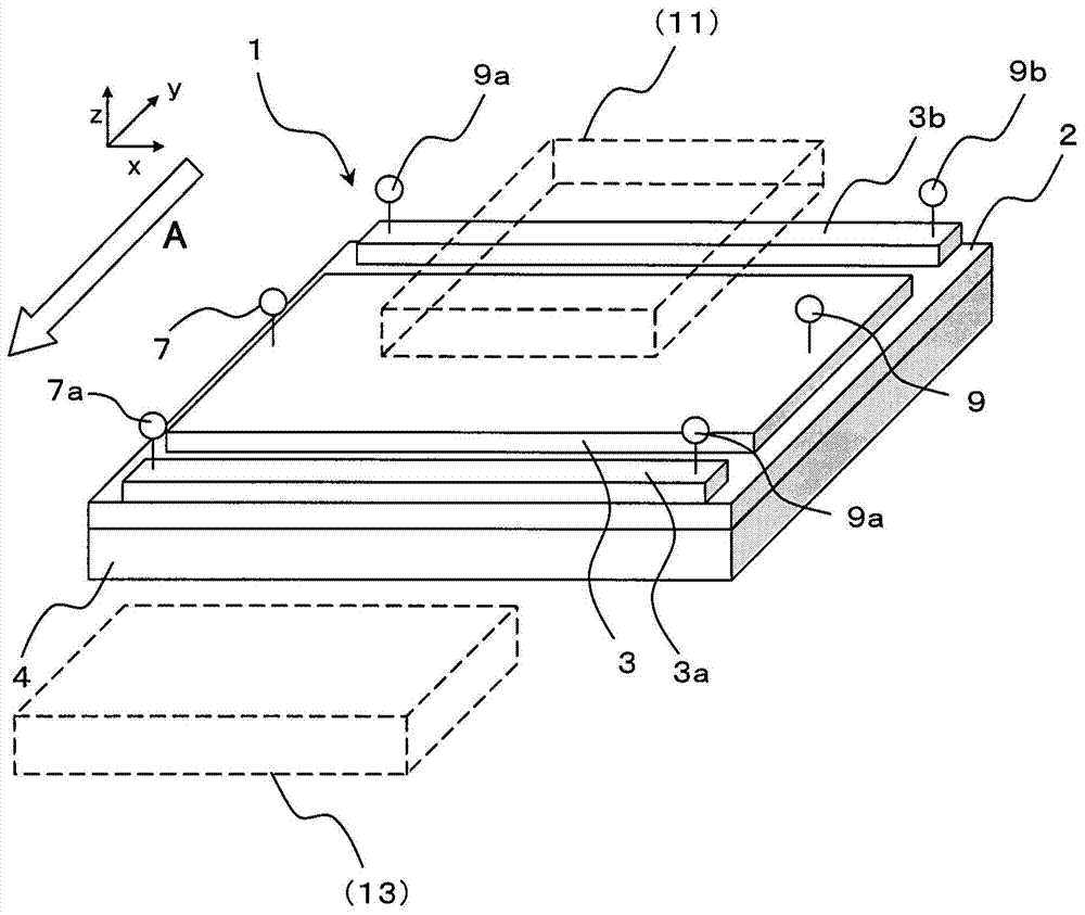
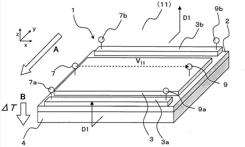
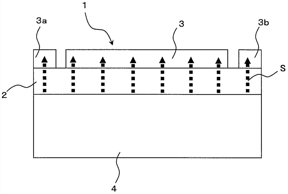
[0230] The thermoelectric conversion element 1 according to the first embodiment was manufactured. Specific steps are as follows:

[0231] First, as for the substrate 4, gallium-gadolinium-gallium garnet (hereinafter referred to as "GGG"; its composition is Gd 3 Ga 5 o 12 ) plane of the substrate (111). As for the magnetic film 2, an yttrium iron garnet film (the composition of which is BiY 2 Fe 5 o 12 ; hereinafter referred to as "Bi:YIG"). For the electrodes 3, 3a and 3b, Pt was used. In this case, the thickness of the GGG substrate was set to 0.7 mm, the thickness of the Bi:YIG film was set to 0.3 mm, and the thickness of the Pt electrode was set to 10 nm.

[0232] The Bi:YIG magnetic film 2 was formed by an aerosol deposition method. As for the raw material of Bi:YIG, Bi:YIG fine particles having a diameter of 300 nm were used. The Bi:YIG fine particles were stored in the aerosol generator container, and the GGG substrate was fixed to a holder provided in the fil...

example 2

[0235] A thermoelectric conversion element 1a according to the second embodiment was manufactured. Specific steps are as follows:

[0236] As the substrate 4a, a thermally conductive anisotropic substrate containing carbon fibers oriented in epoxy resin as a filler was used. The carbon fiber is oriented in a direction perpendicular to the plane with respect to the substrate, and has a large thermal conductivity in this direction.

[0237] As for the magnetic film 2, a yttrium iron garnet film (BiY 2 Fe 5 o 12 ). For the electrodes 3, 3a and 3b, Pt was used. In this case, the thickness of the substrate 4a was set to 0.3 mm, the thickness of the Bi:YIG film was set to 0.1 mm, and the thickness of the Pt electrode was set to 10 nm.

[0238] The Bi:YIG magnetic film 2 was formed by an aerosol deposition method. As for the raw material of Bi:YIG, Bi:YIG fine particles having a diameter of 300 nm were used. Bi:YIG fine particles were stored in the aerosol generator container...

example 3

[0241] A thermoelectric conversion element 1b according to the third embodiment was manufactured. Specific steps are as follows:

[0242] As for the substrate 4b having anisotropic heat conduction characteristics, a polyimide substrate having a thickness of 0.3 mm having a rear surface on which slits are formed, each having a thickness of 0.1 mm, is used. width and depth of 0.2mm.

[0243] As the magnetic film 2, a Bi:YIG film was used. For the electrodes 3, 3a and 3b, Pt was used. In this case, the thickness of the Bi:YIG film was set to 0.1 mm, and the thickness of the Pt electrode was set to 10 nm.

[0244] The Bi:YIG magnetic film 2 was formed by an aerosol deposition method. As for the raw material of Bi:YIG, Bi:YIG fine particles having a diameter of 300 nm were used. The Bi:YIG fine particles were stored in the aerosol generator container, and the substrate 4b was fixed to a holder provided in the film forming chamber. In this state, Bi:YIG fine particles are suck...


PUM


Abstract

The present invention provides a thermoelectric conversion element capable of converting, into electric power, both of the temperature gradient in the in-plane direction and the temperature gradient in the direction perpendicular to a plane at the same time. This thermoelectric conversion element has a substrate (4), a magnetic film (2) that is provided on the substrate (4) and configured by a polycrystalline magnetic insulating material having a component parallel to a film plane and capable of magnetizing in a predetermined direction, and electrodes (3, 3a, 3b) that are provided on the magnetic film (2) and have a material having spin orbit interaction, wherein the temperature gradient perpendicular to a surface of the magnetic film (2) is enabled to be output as a potential difference in an in-plane of one of the electrodes, and the temperature gradient parallel to the surface of the magnetic film (2) is enabled to be output as a potential difference between the electrodes.

Description

technical field [0001] The present invention relates to a thermoelectric conversion element using a magnetic substance and a thermoelectric conversion method. Background technique [0002] In recent years, expectations for thermoelectric conversion elements have been increasing in order to strengthen solutions to environmental and energy issues to achieve sustainable development of society. [0003] This is because heat is the most common source of energy, which can be obtained from various media such as body heat, sunlight, engine and industrial waste heat. [0004] Therefore, thermoelectric conversion elements are expected to become more and more important in the future for improving energy use efficiency in a low-carbon society and for anticipated uses such as for delivering electric power to ubiquitous terminals or sensors. [0005] In order to generate electricity through thermoelectric conversion, it is necessary to properly utilize the temperature difference (tempera...

Claims


Application Information

Patent Timeline
Patent Type & Authority Applications(China)
IPC IPC(8): H01L29/82H01L37/00
CPCH01L37/00H10N15/00
Inventor 桐原明宏中村泰信万伸一内田健一齐藤英治
Owner NEC CORP
Why Eureka
Try Eureka