vehicle power transmission

A power transmission device and power transmission technology, applied in control devices, vehicle components, transportation and packaging, etc., can solve problems such as user injury, damage to other components, time-consuming and labor-intensive problems, and achieve the goal of avoiding collision accidents and improving safety Effect

Inactive Publication Date: 2016-06-29
KYMCO
View PDF6 Cites 0 Cited by
  • Summary
  • Abstract
  • Description
  • Claims
  • Application Information

AI Technical Summary

Problems solved by technology

[0006] However, using manual control is not only time-consuming and labor-intensive, but also a little carelessness when pulling, the user may collide with other components of the vehicle 100, causing damage to other components, and even causing injury to the user

Method used


Image

  • vehicle power transmission
  • vehicle power transmission
  • vehicle power transmission

Examples


Embodiment Construction

[0018] The aforementioned and other technical contents, features and effects of the present invention will be clearly presented in the following detailed description of a preferred embodiment with reference to the accompanying drawings.

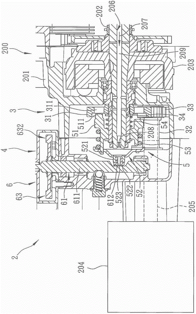
[0019] refer to figure 2 , a preferred embodiment of the power transmission device 2 of the vehicle of the present invention, the vehicle 200 includes an engine 201 with a crankshaft 202, an alternator 203 arranged on the crankshaft 202, an external hanger arranged at intervals with the engine 201 The generator 204 and a lubricating passage 206 formed in the crankshaft 202 along the length direction of the crankshaft 202 and through which lubricating oil 207 flows. The electric power generated by the alternator 203 is used to charge the battery (not shown) of the vehicle 200 , and the shaft 205 of the external generator 204 is on a different axis from the crankshaft 202 .

[0020] The power transmission device 2 includes a power transmissio...


PUM


Abstract

Provided is a vehicle power transmission device. A vehicle comprises an engine with a bent axle, an AC generator and a plug-in generator. The power transmission device comprises a power transmission unit and a switching unit. The power transmission unit comprises a power output gear which is arranged on the bent axle in a sleeved mode, a power transmission mechanism which is connected with the plug-in generator, and a power transmission gear which is meshed with the power output gear. The switching unit comprises a switching mechanism which is connected with the bent axle and the power output gear in a controlled mode, and an electric driving mechanism which is used for driving the switching mechanism. The electric driving mechanism is used for driving the switching mechanism, time and labor can be saved, collision accidents probably happening in the process of manual pulling switching can further be effectively avoided, and the safety is greatly improved.

Description

technical field [0001] The present invention relates to a transmission device, in particular to a vehicle power transmission device. Background technique [0002] refer to figure 1 , China Taiwan Publication No. 201203812 "Vehicle Power Generation Device" patent case, wherein the vehicle 100 includes an engine 101 with a crankshaft 102, a charging generator 103 driven by the crankshaft 102, and a power supply generator 104 , and the power generating device 1 includes a clutch unit 11 and a transmission unit 12 . [0003] The clutch unit 11 includes a switching clutch 111 disposed on the crankshaft 102 , a driving gear 112 disposed on the switching clutch 111 , and a switching mechanism 113 capable of actuating the switching clutch 111 . [0004] The switch mechanism 113 includes a switch shaft 114 pivotally passed through the engine 101 , and a puller 115 disposed on the switch shaft 114 and located outside the engine 101 . The transmission unit 12 includes a driven gear ...

Claims


Application Information

Patent Timeline
Patent Type & Authority Patents(China)
IPC IPC(8): B60K17/04B60K17/28
Inventor 王俊凯何昭昌
Owner KYMCO
Why Eureka
Try Eureka