
Non-contact limiting device

A limit device and non-contact technology, which is applied in the direction of railway signals and safety, can solve problems such as potential safety hazards, failure of stroke control, and impact on production efficiency, so as to improve reliability and safety, solve potential safety hazards, and eliminate The effect of safety hazards

Pending Publication Date: 2020-05-05
石钢京诚装备技术有限公司
View PDF0 Cites 0 Cited by
  • Summary
  • Abstract
  • Description
  • Claims
  • Application Information

AI Technical Summary

Problems solved by technology

However, the stroke control device cannot satisfy the independent stroke control between the running mechanisms, so collision accidents between the running mechanisms are very easy to occur
[0004] The fixed guide rails are all set in the main passage area, and rigid stoppers are installed between each traveling mechanism, which can easily affect the passage of other vehicles and personnel, and there are potential safety hazards
And due to the height of the rigid stop and the uneven floor of the production workshop, it is very easy to cause the rigid stop and the stroke opening to be scratched, or the travel switch cannot be in contact with the rigid stop, which eventually leads to the failure of the stroke control
[0005] If you use other non-contact stroke control methods, such as non-contact stroke control using infrared or laser detection, you need to install a feedback board about 200mm high on the ground to achieve stroke control. All institutions will stop running, posing safety hazards and affecting production efficiency

Method used


Image

  • Non-contact limiting device
  • Non-contact limiting device
  • Non-contact limiting device

Examples


Embodiment Construction

[0035] The present invention will be described in further detail below in conjunction with the examples.

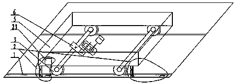
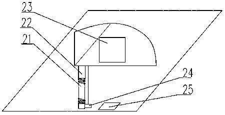
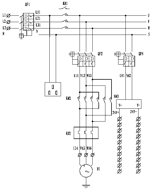
[0036] The invention discloses a non-contact limit device, which is arranged on the front and rear ends of each traveling mechanism, including a mechanical connection mechanism and an electrical detection system, wherein the mechanical connection mechanism includes a fixed bracket 21 arranged at the lower part of the traveling mechanism, installed on The elastic deformation mechanism 22 on the fixed support 21; the electrical detection system includes an electric control box 23 installed on the outer surface of the running mechanism, a detection switch 24 installed on the elastic deformation mechanism 22, and a control panel fixed on the independent working area of ​​each running mechanism. The feedback board 25 on the ground at both ends, the detection switch 24 is matched with the feedback board 25 correspondingly;

[0037] The electric control box 23 is provided with a...


PUM


Abstract

The invention relates to a non-contact limiting device. The device comprises a mechanical connection mechanism and an electrical detection system, wherein the mechanical connection mechanism comprisesa fixing support and an elastic deformation mechanism, the electrical detection system comprises a detection switch and a feedback plate, an electric control box fixing support is installed on a lower portion of a fixed rail walking mechanism, an elastic deformation mechanism is installed on the fixing support, a detection switch is installed on the elastic deformation mechanism through the fixing support, feedback plates are flatly laid and fixed to the ground at two ends of an independent working area of each walking mechanism, and an electric control box is installed on a side face of eachwalking mechanism to achieve electric control. The device is advantaged in that running safety of the walking mechanism is improved, collision accidents are avoided, potential safety hazards existingat present are eliminated, stability of production running is ensured, collision accidents are avoided, potential safety hazards are eliminated, and production efficiency is improved.

Description

technical field [0001] This patent application belongs to the technical field of railway track maintenance and processing equipment, and more specifically relates to a non-contact limiting device. Background technique [0002] In heavy industry production workshops, workpieces are carried on the ground by embedding a fixed guide rail on the main passage in the factory building, and then arranging multiple walking mechanisms on the guide rails to meet the needs of carrying workpieces to different production workshops to perform multiple processes. The traveling mechanism is composed of a mechanical frame, traveling wheels, a mechanical transmission system, an electrical control system, and a stroke control device. The mechanical frame acts on the traveling wheels through the mechanical transmission system. The traveling wheels run along the fixed track through the wheel rim. The electrical control system controls the traveling wheels to start and stop on the fixed guide rail ...

Claims


Application Information

Patent Timeline
IPC IPC(8): B61L23/00
CPCB61L23/00
Inventor 张海龙张晓玲
Owner 石钢京诚装备技术有限公司
Learn More