
Automatic break sealing machine for heat shrinking tube

An automatic cutting and sealing machine technology, applied in packaging sealing/fastening, external support, transportation packaging, etc., can solve the problems of unstable sealing quality, many sealing actions, and low sealing efficiency, so as to reduce sealing time and reduce sealing Action, the effect of reducing material waste

Active Publication Date: 2014-04-16
CHANGYUAN ELECTRONICS DONGGUAN +3
View PDF5 Cites 6 Cited by
  • Summary
  • Abstract
  • Description
  • Claims
  • Application Information

AI Technical Summary

Problems solved by technology

[0003] The technical problem to be solved by the present invention is: in order to overcome the defects of many sealing actions, long time, low sealing efficiency, unstable sealing quality and waste of materials during sealing in the existing heat-shrinkable tube packaging, the present invention provides a heat-shrinkable tube automatic Cutting off the sealing equipment can effectively reduce the sealing action, reduce the sealing time (the sealing time is only 3.5S-5S), improve the sealing quality, and greatly reduce the material waste caused by sealing (only 4CM is wasted at the sealing part of each plate)

Method used


Image

  • Automatic break sealing machine for heat shrinking tube
  • Automatic break sealing machine for heat shrinking tube
  • Automatic break sealing machine for heat shrinking tube

Examples


Embodiment Construction

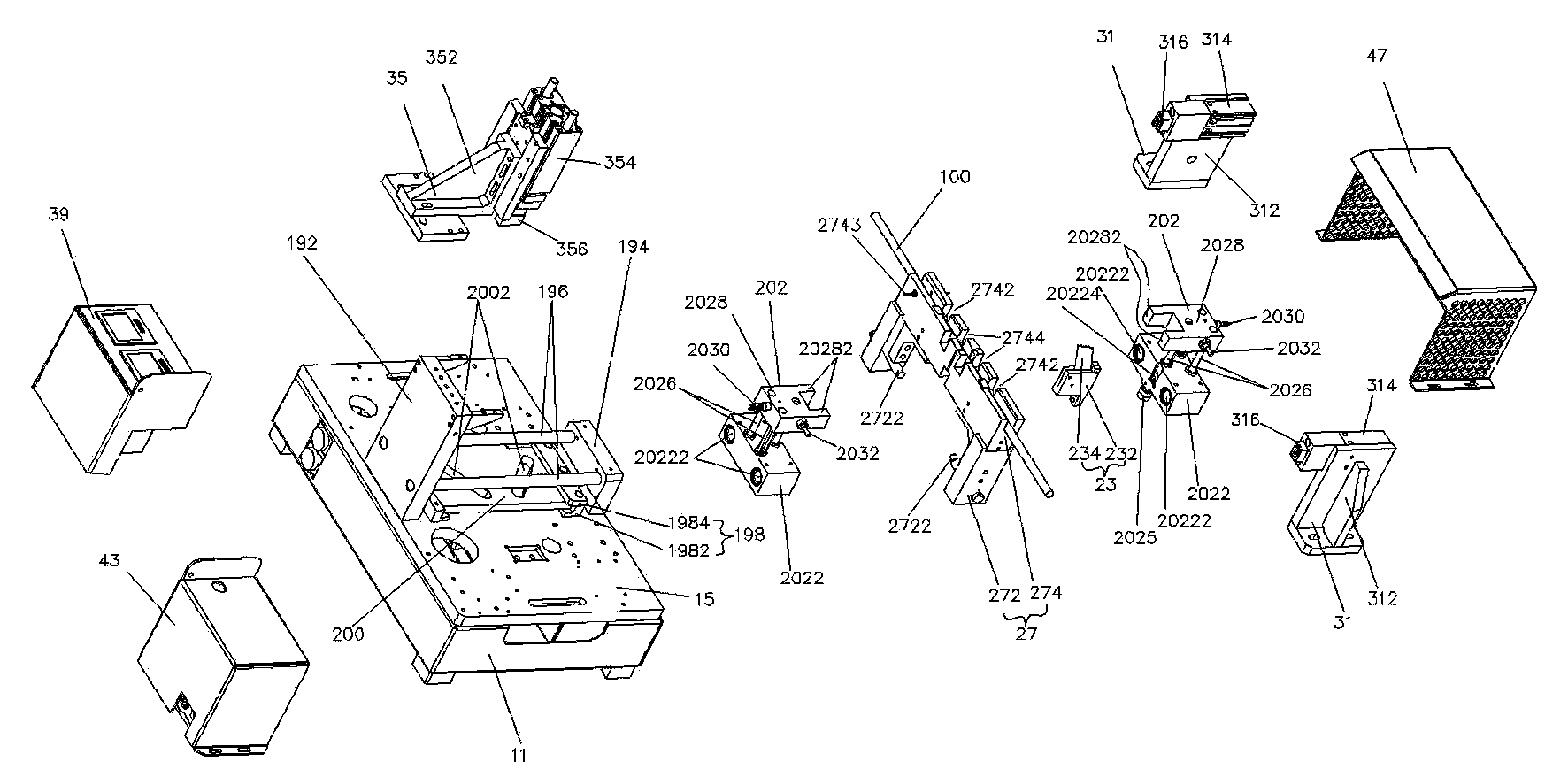
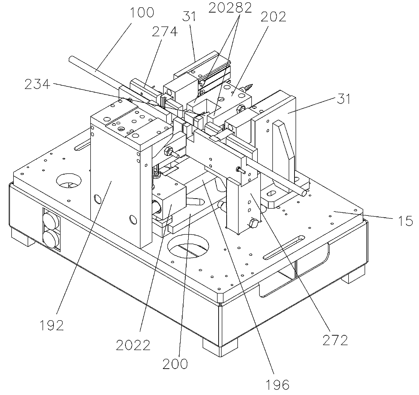
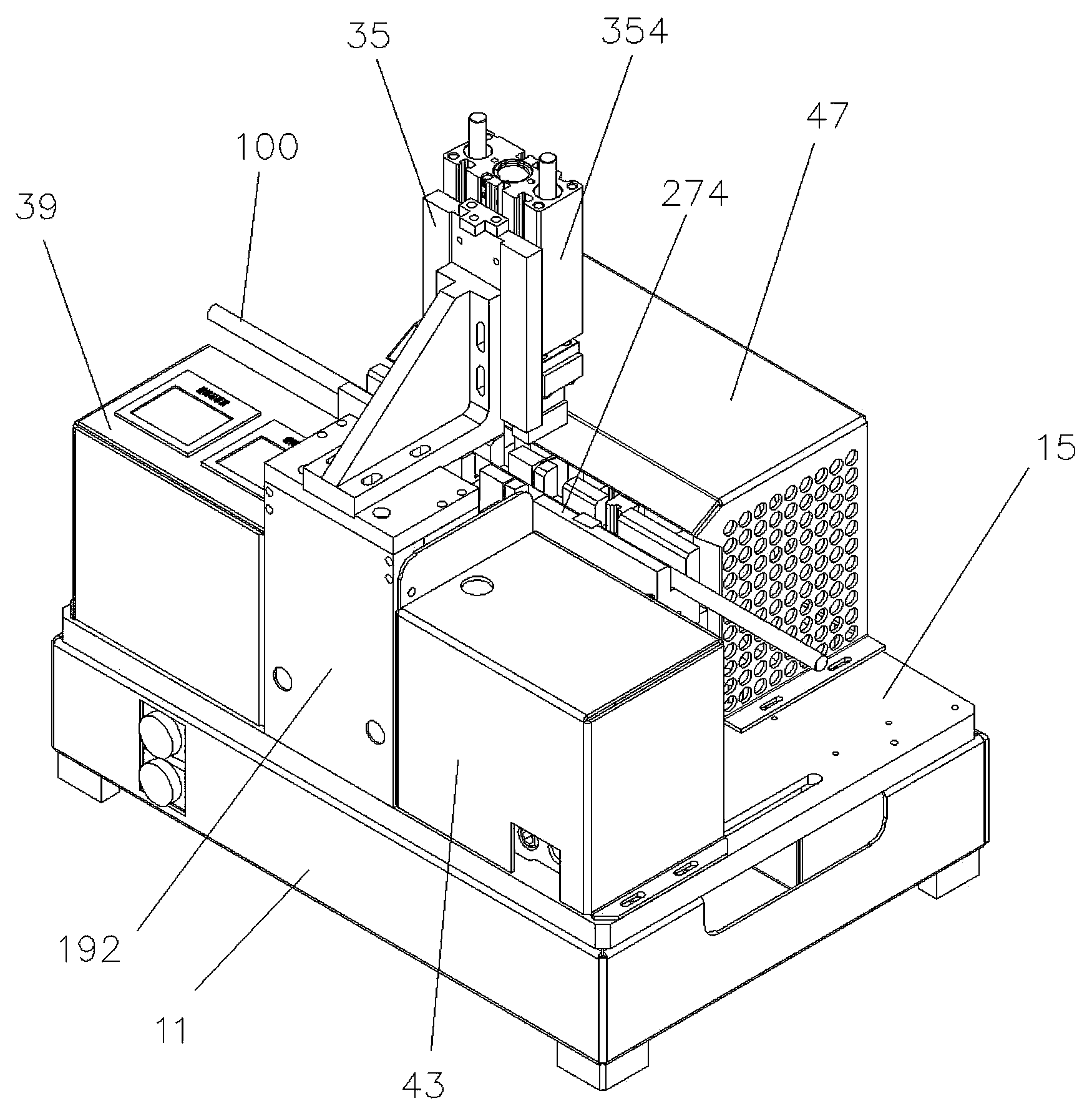
[0041] see Figure 1 to Figure 4 , a heat-shrinkable tube automatic cutting and sealing machine, including an electric control box 11, a mounting base 15, a heating mechanism (unlabeled), a cutting mechanism 23, a channel mechanism 27, two pressing and holding mechanisms 31, a Cooling compression mechanism 35, a temperature controller 39, a pneumatic control installation box 43, a safety shield 47.

[0042] A power switch (not labeled) is installed on the electric control box 11 .

[0043] The installation bottom plate 15 is fixedly installed on the top of the electric control box 11 .

[0044] The heating mechanism includes a front mounting block 192 , a rear mounting block 194 , two sliding rods 196 , two chute assemblies 198 , a stroke control sliding plate 200 , and two heating assemblies 202 .

[0045] The front mounting block 192 is fixedly mounted on the front edge of the mounting base 15 .

[0046] The rear mounting block 194 is fixedly mounted on the rear edge of t...


PUM


Abstract

An automatic break sealing machine for a heat shrinking tube comprises a mounting bottom plate, a heating mechanism, a cutting mechanism, a flow channel mechanism and an air compressing mechanism. The heating mechanism comprises a plurality of sliding rods, sliding groove assemblies, a stroke control sliding plate and heating assemblies. A sliding groove is formed between the two sliding groove assemblies, and the stroke control sliding plate is inserted into the sliding groove and slides in the lateral direction of the sliding groove. Two stroke control grooves are formed in the stroke control sliding plate, each heating assembly comprises a supporting sliding block, a bottom shaft and a heating block, the bottom shaft is arranged at the bottom of the supporting sliding block, a rolling bearing is arranged on the bottom shaft, the two heating assemblies are arranged on a plurality of sliding rods and can slide along the sliding rods, and the rolling bearings are correspondingly inserted in the stroke control grooves. The flow channel mechanism comprises two sliding channel vertical columns and a flow channel, and the flow channel is arranged on the two flow channel vertical columns and cross the sliding rods from above. The automatic break sealing machine for the heat shrinking tube effectively reduces seal time, improves seal efficiency, improves seal quality, and reduces material waste.

Description

technical field [0001] The invention relates to a device for automatically cutting and sealing heat-shrinkable tubes in the heat-shrinkable tube industry. This equipment can not only effectively reduce the sealing time of heat-shrinkable tube packaging, improve the sealing efficiency of heat-shrinkable tubes, but also greatly improve the sealing quality and reduce the material waste caused by sealing. Background technique [0002] At present, in heat-shrinkable tube packaging, it is usually necessary to fill the heat-shrinkable tube with a certain pressure of gas before packaging, so as to prevent the heat-shrinkable tube from being squeezed and deformed after packaging. In order to ensure that the gas does not leak, the two ends of the heat shrinkable tube should be sealed. At present, the commonly used sealing method is manual sealing. The method is that after the heat-shrinkable tube is filled with a certain pressure gas, the operator folds the heat-shrinkable tube in th...

Claims


Application Information

Patent Timeline
Patent Type & Authority Applications(China)
IPC IPC(8): B65B51/14B65B51/32B65B61/06
Inventor 刘智勇柏禹喻锋常伟锋刘晓播
Owner CHANGYUAN ELECTRONICS DONGGUAN
Learn More