A kind of plastic bracket for sub-collector

A technology of plastic brackets and water collectors, which is applied in the direction of pipeline brackets, hot water central heating systems, thin plate connections, etc., can solve the problems of many processing procedures, inconvenient adjustments, poor aesthetics, etc., and achieve a reasonable use of the overall structure and high market value. Good competitiveness and product consistency

Inactive Publication Date: 2016-02-03
PINGJIANG SHENGYING MICA IND
View PDF10 Cites 2 Cited by
  • Summary
  • Abstract
  • Description
  • Claims
  • Application Information

AI Technical Summary

Problems solved by technology

At present, the brackets used for the sub-catchment are all made of iron, and the up and down adjustment structure is connected by fasteners, and there are many accessories; tools such as wrenches are needed, which is inconvenient to adjust; the aesthetics are poor; the product has many processing procedures and high cost.

Method used


Image

  • A kind of plastic bracket for sub-collector
  • A kind of plastic bracket for sub-collector
  • A kind of plastic bracket for sub-collector

Examples


Embodiment 1

[0026] The plastic bracket of the sub-water collector in the first embodiment is made of PA6, or plastic materials such as POM, PC, ABS, and PPS. The square nut 4 can also be fixed in the form of an injection molded insert, such as an insert nut commonly used on plastic parts. The rubber pad can be removed under the condition that the support can hold the manifold tightly, or a rubber pad of other shapes can be used to increase the holding force. There may be one, two or more first hook columns 21 on the bottom of the upper bracket 20 and second hook columns 31 on the lower bracket 30 .

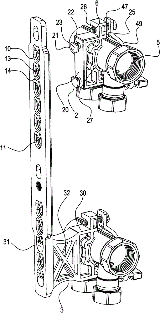
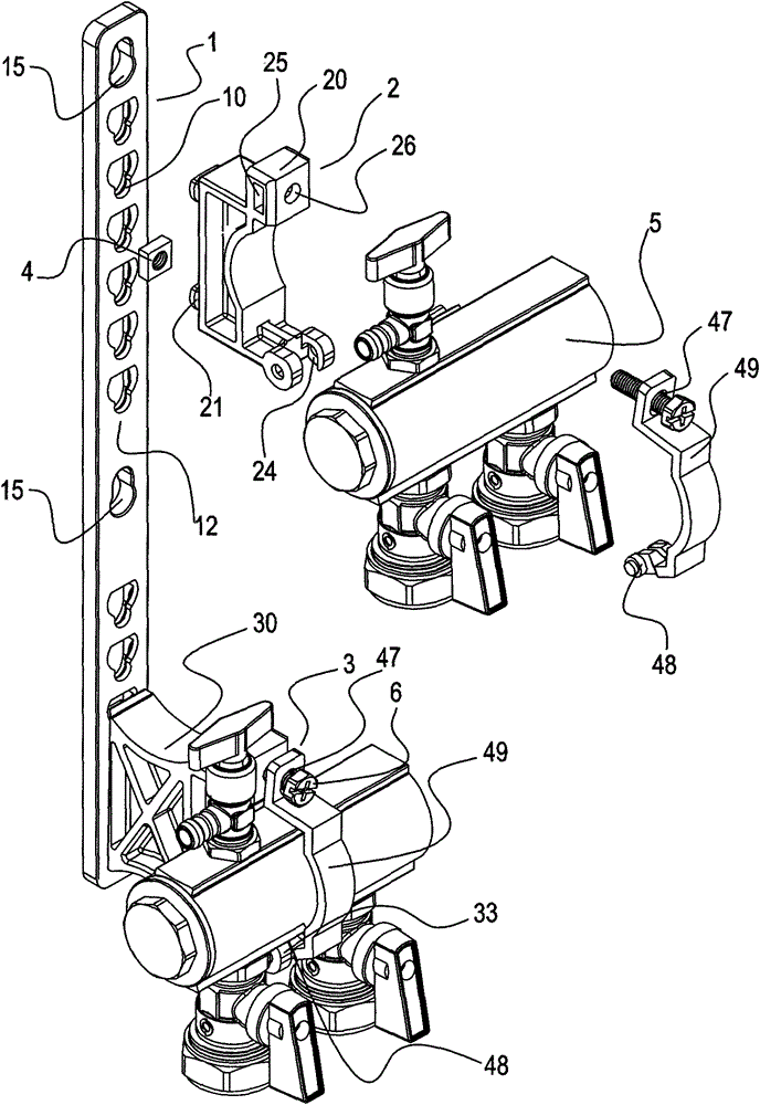
[0027] image 3 The shown second embodiment of the plastic bracket of the sub-collector has a structure similar to that of the first embodiment. The shape of the fixed sub-catchment 5 of the second embodiment is also different from that of the first embodiment.

Embodiment 2

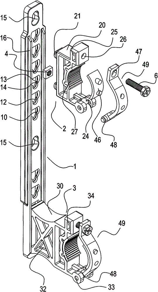
[0028] The water collector plastic bracket of the second embodiment includes an adjusting frame 1 , an upper fixing frame 2 and a lower fixing frame 3 movably fixed on the adjusting frame 1 . The adjusting frame 1 is a strip body, and the adjusting frame 1 is provided with a row of draw-in slots 10; the adjusting frame 1 is also provided with two screw holes 15 for fixing the wall, which are respectively distributed on the top and the middle of the adjusting frame 1.

[0029] The upper fixed frame 2 mainly includes an upper bracket 20 and a movable part 49 . At the bottom of the upper bracket 20 are two first hook posts 21 fixedly fitted with the slots 10 of the adjustment frame 1 . The shape of the movable part 49 fits the shape of the sub-catchment 5, and there is an arc in the middle, and a cylindrical pin 48 is provided at its tail, which is rotatably fixed with the first pin groove 24 at the lower end of the upper bracket 20. The other end of the movable part 49 has a sc...


PUM


Abstract

The invention relates to fixed pipeline equipment, and particularly relates to a water dividing and collecting device bracket. The plastic bracket of the water dividing and collecting device comprises an adjusting rack (1), an upper fixing rack (2) and a lower fixing rack (3), wherein the upper fixing rack (2) and the lower fixing rack (3) are adjustably fixed on the adjusting rack (1); a row of necks (10) are formed in the adjusting rack (1); the front end part (12) of each neck (10) forms an inverse calabash shape on the whole; a reducing structure (14) exists on a waist part (13) of the inverse calabash shape; a first hook post (21) is arranged at the bottom of an upper bracket (20) of the upper fixing rack (2); fixed matching is achieved by the first hook post and the necks (10) in the fixing process. According to the plastic bracket of water dividing and collecting device, which is disclosed by the invention, the main body is made of a plastic material, and is lighter and more applicable to an operating environment; the plastic bracket is integrally molded in an injection manner, fewer in component and convenient to process; the adjusting rack and the fixing rack are connected by adopting a buckle structure, and fast to fix; the fixing rack can be adjusted up and down, more flexible to install, practical and reasonable in overall structure, and strong in exploitativeness.

Description

technical field [0001] The present invention relates to fixed pipeline equipment, in particular to the sub-collector support. Background technique [0002] The brackets are widely used, such as camera tripods, solar brackets, pipe hangers and pipe clamps in the construction field, etc., which can improve the stability of the fixed objects and improve the space utilization. [0003] The structure of the sub-catchment bracket in the prior art is similar to the "Water sub-catchment bracket" of the authorized announcement number CN202674534U. The two ends of the sub-catchment bracket are connected to the main frame of the sub-catchment by screws, and the upper and lower two sub-collectors The main frame is respectively provided with movable slots and fixed holes, and the distance between the fixed frames is adjusted up and down through fasteners. There is also the prior art of "Sub-Catcher Bracket" such as authorized announcement number CN202349550U. Two vertical bars and beams...

Claims


Application Information

Patent Timeline
Patent Type & Authority Patents(China)
IPC IPC(8): F16L3/237F16L3/10
CPCF16L3/1091F16L3/237F16B5/0642F16B5/0664F16B21/09F16L3/1075F16L3/243F16L55/035F24D3/1066F16B1/00
Inventor 黄晓峰
Owner PINGJIANG SHENGYING MICA IND
Why Eureka
Try Eureka