Hydraulic control butterfly valve

A hydraulic control butterfly valve, butterfly valve technology, applied in the direction of lifting valve, valve device, engine components, etc., can solve the problem of reducing the accuracy and reliability of the hydraulic control butterfly valve action feedback signal, the adjustment position cannot be completed accurately, and the work efficiency of maintenance personnel is affected. problem, to achieve the effect of simple structure, flexible use and easy realization

Active Publication Date: 2019-03-26
GUANGDONG DATANG INT CHAOZHOU POWER GENERATION
View PDF5 Cites 0 Cited by
  • Summary
  • Abstract
  • Description
  • Claims
  • Application Information

AI Technical Summary

Problems solved by technology

Sometimes, the adjustment of the position cannot be completed accurately at one time, and it may be necessary to open the hole multiple times
This greatly affects the work efficiency of maintenance personnel
At the same time, it also greatly reduces the accuracy and reliability of the hydraulic control butterfly valve action feedback signal

Method used


Image

  • Hydraulic control butterfly valve
  • Hydraulic control butterfly valve
  • Hydraulic control butterfly valve

Examples


Embodiment 1

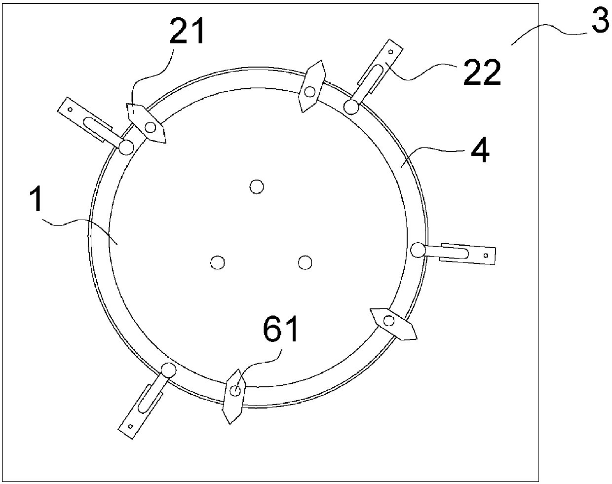
[0046] Such as image 3 , Figure 4 As shown, the hydraulic control butterfly valve in this embodiment includes a rotating disk 1, a butterfly valve bracket 3 matched with the rotating disk 1, and a stroke feedback device installed thereon. The travel feedback device includes: a circumferential groove 4 located on the outer circumferential position of the rotating disk 1, the notch 41 of which is opened forward, and the radial dimension of the groove bottom 42 is larger than the radial dimension of the notch 41, so that its section is inverted T-shaped; And the limit switch 22 located on the butterfly valve bracket 3, used to control the transmission of the feedback signal; and the touch module 21 located on the rotating disk 1, which rotates with the rotating disk 1, used to touch the limit switch 22; and the connecting piece, its two ends Connect with the touch module 21 and the groove bottom 42 of the circumferential groove 4 respectively, the radial dimension of one end o...

Embodiment 2

[0048] Such as Figure 5 , Figure 6 As shown, the difference between this embodiment and the above-mentioned embodiments is that a mounting hole 7 is provided at the position corresponding to the circumferential groove 4 at the rear of the rotating disk 1, and the radial dimension of the mounting hole 7 is larger than the dimension along the direction at the end of the connecting piece at the bottom of the groove. , so that the end of the connector located at the bottom of the groove can be placed in the bottom of the circumferential groove 42 from the mounting hole 7 . And the connectors in this embodiment are screws 61 and nuts 62 that cooperate with each other. The screws 61 are inserted into the corresponding holes on the touch module 21 from the front and penetrate the notch 41. The nuts 62 are inserted into the bottom of the circumferential groove 4 from the installation hole 7 42 and tighten with screw 61.

[0049] The number of mounting holes 7 in this embodiment ma...

Embodiment 3

[0051] Such as Figure 7 , Figure 8 As shown, the difference between this embodiment and the above-mentioned embodiments is that the travel feedback device also includes an auxiliary part 5, which is used to assist the movement and positioning of the touch module 21, which is arranged on the rear side of the touch module 21 and located in the notch 41 Among them, the dimension along the radial direction of the rotating disk 1 is slightly smaller than or equal to the dimension of the notch 41 along this direction, and a through hole is provided on it, which can be connected with the touch module 21 as a whole through a connecting piece. The auxiliary part can prevent the screw 61 from tilting and shaking relative to the axial direction in the notch, thereby avoiding affecting the sensitivity of the travel feedback device. Moreover, when adjusting the stroke feedback device, the auxiliary part can also reduce or even avoid friction between other parts and the notch, which is m...


PUM


Abstract

The invention discloses a hydraulic control butterfly valve. The hydraulic control butterfly valve comprises a rotating disc, a butterfly valve bracket matched with the rotating disc, and a stroke feedback device arranged on the butterfly valve; the stroke feedback device further comprises a circumferential groove located in the circumferential position of the outer side of the rotating disc, a groove opening of the circumferential groove is formed forwards, the radial size of the groove bottom of the circumferential groove is greater than that of the groove opening of the circumferential groove; and the radial size of the end, located in the groove bottom, of a connecting piece is greater than the size of the groove opening in the direction, thus a touch module is fixedly connected to thecircumferential groove and can be slidably adjusted along the circumferential groove. The stroke feedback device of the hydraulic control butterfly valve can be flexibly adjusted according to the using environment and using conditions, the adjusting mode is simple and easy to realize, and the structure of the butterfly valve cannot be damaged either.

Description

technical field [0001] The invention belongs to the field of fluid control, and in particular relates to a hydraulic control butterfly valve. Background technique [0002] Hydraulically controlled butterfly valves in the prior art, such as figure 1 As shown, it includes a rotary disk 1', a butterfly valve bracket 3' matched with the rotary disk 1', and a stroke feedback device. The stroke feedback device includes a stroke switch 22' and a touch module 21' matched with it. The cross-sectional structure of the rotary disk 1' Such as figure 2 shown. When the user adjusts the position of the hydraulic control butterfly valve, the rotary plate 1 rotates and drives the touch module 21' on it to rotate. The touch module 21' cooperates with the travel switch 22', and the travel switch 22' feeds back the signal to the control system , to coordinate the controller's operations. The correctness and reliability of the hydraulic control butterfly valve action feedback signal is of g...

Claims


Application Information

Patent Timeline
IPC IPC(8): F16K1/22F16K37/00
CPCF16K1/22F16K37/00
Inventor 陈德霖张久洲黄勇郭凌云许统彬刘春娟
Owner GUANGDONG DATANG INT CHAOZHOU POWER GENERATION
Why Eureka
Try Eureka