Waterproof structure and mobile phone utilizing the same

A technology of waterproof structure and housing, which is applied to the structure of telephones and sealed casings, etc., which can solve problems such as low yield rate, increased difficulty in waterproofing, and inability to guarantee manufacturing tolerances, etc.

Active Publication Date: 2014-04-16
POWER IDEA TECH (SHENZHEN) CO LTD
View PDF7 Cites 6 Cited by
  • Summary
  • Abstract
  • Description
  • Claims
  • Application Information

AI Technical Summary

Problems solved by technology

In the above two waterproof structures, because the waterproof soft rubber has a full-circle structure and the cross-section of the soft rubber is small, the manufacturing tolerance cannot be guaranteed, resulting in an increase in the cumulative tolerance. At the same time, the waterproof soft rubber needs to be manually placed in the corresponding position, which increases the Assembly process, poor operation reliability, and low yield; in addition, because the waterproof soft rubber and the front and rear shells are formed separately, after pressing, it is necessary to ensure that the waterproof soft rubber and the contact surface of the front shell and the rear shell are sealed and waterproof at the same time. Increased the difficulty of waterproofing. In addition, because the waterproof effect of this structure is mainly determined by the degree of pressing and sealing between the soft waterproof rubber and the contact surface of the front shell and the contact surface of the rear shell, the strength of the shell, the flatness of the location of the soft waterproof rubber, and There are relatively high requirements for the position and spacing of the locking screws of the front and rear shells, and the pulling force of the hot-melt nuts.

Method used


Image

  • Waterproof structure and mobile phone utilizing the same
  • Waterproof structure and mobile phone utilizing the same
  • Waterproof structure and mobile phone utilizing the same

Examples


Embodiment Construction

[0015] In order to make the purpose, technical solution and advantages of the present invention more clear, the waterproof structure of the present invention and the mobile phone using the waterproof structure will be further described below in conjunction with the drawings and specific embodiments.

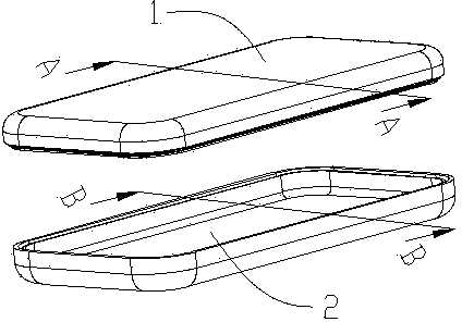
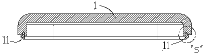
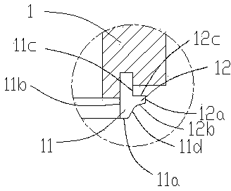
[0016] Please refer to figure 1 , figure 2 , image 3 , Figure 4 and Figure 5 , which is a mobile phone waterproof structure embodiment, the mobile phone includes a front shell 1 and a rear shell 2, the front shell 1 is provided with a soft material protrusion structure 11, the soft material protrusion mechanism 11 and The front shell 1 is integrally double-shot molded, and the raised structure 11 includes a first top surface 11a, a first inner surface 11b, and a first outer surface 11c, and the first outer surface 11c is close to the first top surface 11a for ease of assembly And set a guide slope 11d, on the first outer surface 11c of the protruding structure 11, a bump ...


PUM


Abstract

The invention relates to a waterproof structure and a mobile phone utilizing the waterproof structure. The waterproof structure comprises a first shell and a second shell, wherein a first shell and a second shell are assembled together. The first shell is provided with a convex structure and the second shell is provided with a groove and at least one of them is made of soft material. The soft material and a corresponding shell are integrally formed and the convex structure and the groove are in interference fit. Through the interference fit, waterproof effect can be achieved between a front shell and a rear shell. Besides, to more effectively ensure the waterproof effect, a bump structure is further mounted in the side of inner surface of the convex structure. The bump structure is in interference fit with the groove side wall, thereby achieving double protection in waterproof effect between the front and rear shell. The invention further relates to a mobile phone utilizing the waterproof structure. Through the application of the waterproof structure between the front shell and the rear shell, waterproof effect between the front shell and the rear shell is effectively ensured, the assembly process is made simple and convenient, and production efficiency is promoted.

Description

technical field [0001] The invention relates to a waterproof structure and a mobile phone using the waterproof structure. Background technique [0002] In recent years, with the increase of people's outdoor activities, outdoor products have been used more and more, waterproof mobile phones have emerged as the times require, and achieving good waterproof has always been the goal of the industry. Among the various waterproof levels of waterproof mobile phones , the waterproofing of the front and rear shells is the biggest technical difficulty. The waterproof structure of the front and rear shells of the prior art waterproof mobile phone usually includes a front shell, a shell waterproof soft rubber and a rear shell, a circle of grooves is arranged on the rear shell, and the waterproof soft rubber shell is placed on the In the groove, the front and rear shells press and squeeze the waterproof soft rubber of the shell to realize the waterproofing of the front and rear shells. ...

Claims


Application Information

Patent Timeline
Patent Type & Authority Applications(China)
IPC IPC(8): H04M1/02H05K5/06
Inventor 马继东陈东明
Owner POWER IDEA TECH (SHENZHEN) CO LTD
Why Eureka
Try Eureka