Self-locking bolt assembly

A bolt assembly and self-locking technology, which is applied in the direction of locking fasteners, bolts, threaded fasteners, etc., can solve problems such as inconvenient use, reduced mechanical strength of bolts, and increased cost of bolts

Pending Publication Date: 2021-01-01
邹吉武
View PDF2 Cites 0 Cited by
  • Summary
  • Abstract
  • Description
  • Claims
  • Application Information

AI Technical Summary

Problems solved by technology

[0002] At present, most self-locking bolts and nuts use special processing technology or attached structure to achieve the purpose of locking. The special processing technology increases the cost of the bolt and reduces the overall mechanical strength of the bolt, while

Method used


Image

  • Self-locking bolt assembly
  • Self-locking bolt assembly
  • Self-locking bolt assembly

Examples


Embodiment Construction

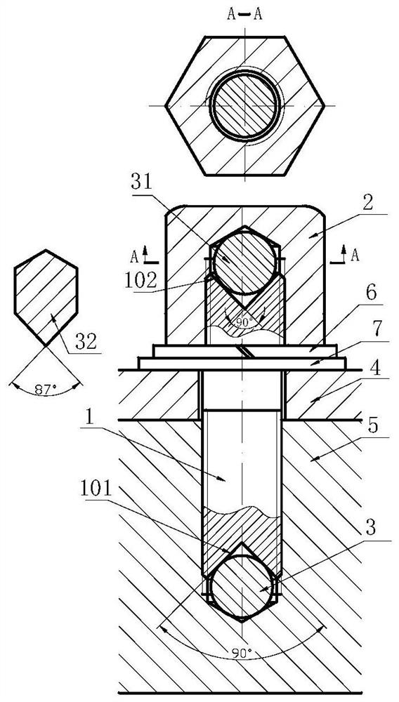
[0010] combine figure 1 , the two ends of the stud bolt 1 have tapered sockets, the conical angles of the tapered sockets 101 and 102 are both 90 degrees, the thread of the blind hole of the fastened part 5 is matched with the thread of the stud bolt 1, using The metal ball expansion block 3 whose diameter is slightly smaller than the diameter of the round hole is put into the thread of the blind hole, the stud bolt 1 is added to the spring washer 6 and the adjustment flat washer 7 and passes through the opening of the connected part 4, and screwed into the connected part In the thread of the blind hole of part 5, a pad 32 without locking function is put into the tapered socket 102 at the outer end of the stud bolt. Since the taper angle of the pad 32 is less than 90 degrees, in this example The taper angle is 87 degrees, and there will be no radial expansion force when placed in the taper socket 102 of the bolt 1; the cap nut 2 is screwed into the outside of the stud bolt 1, ...


PUM

PropertyMeasurementUnit
Cone angleaaaaaaaaaa

Abstract

The invention relates to a self-locking bolt assembly. The self-locking bolt assembly comprises a bolt with a conical nest hole, an expansion block and a cover-shaped nut, wherein the bolt, the expansion block and the cover-shaped nut are easy to machine, the mechanical strength of the bolt is not affected, mounting and dismounting are easy, the tension borne by the bolt is reduced while the boltand the cover-shaped nut are locked, and the load bearing capacity of the bolt is improved.

Description

technical field [0001] The invention relates to a self-locking bolt assembly, in particular, it provides a bolt with a tapered socket, an expansion block and a cap nut matched with the tapered socket, which are used for couplings and fastening In the case of parts, it has the function of self-locking and the body structure is simple, which can reduce the tension on the bolt and increase the mechanical strength of the bolt when fastening or connecting. Background technique [0002] At present, most self-locking bolts and nuts use special processing technology or attached structure to achieve the purpose of locking. The special processing technology increases the cost of the bolt and reduces the overall mechanical strength of the bolt, while the self-locking structure with attached structure Bolts bring inconvenience to use. The existing published invention patents 201510462312.9 and 201822082675.1 have complex structures and difficult processing, which also reduces the mechan...

Claims


Application Information

Patent Timeline
IPC IPC(8): F16B35/04F16B39/282
CPCF16B35/041F16B39/282
Inventor 邹吉武
Owner 邹吉武
Why Eureka
Try Eureka