Hand-held type working machine

A working machine, hand-held technology, applied in the direction of machine/engine, mechanical equipment, engine components, etc., to achieve the effect of simple structure, reduced vibration transmission, and reduced vibration transmission

Inactive Publication Date: 2008-02-13
ANDREAS STIHL AG & CO KG
View PDF1 Cites 4 Cited by
  • Summary
  • Abstract
  • Description
  • Claims
  • Application Information

AI Technical Summary

Problems solved by technology

This leads to an increased weight of the exhaust muffler and thus of the entire working machine

Method used


Image

  • Hand-held type working machine

Examples


Embodiment Construction

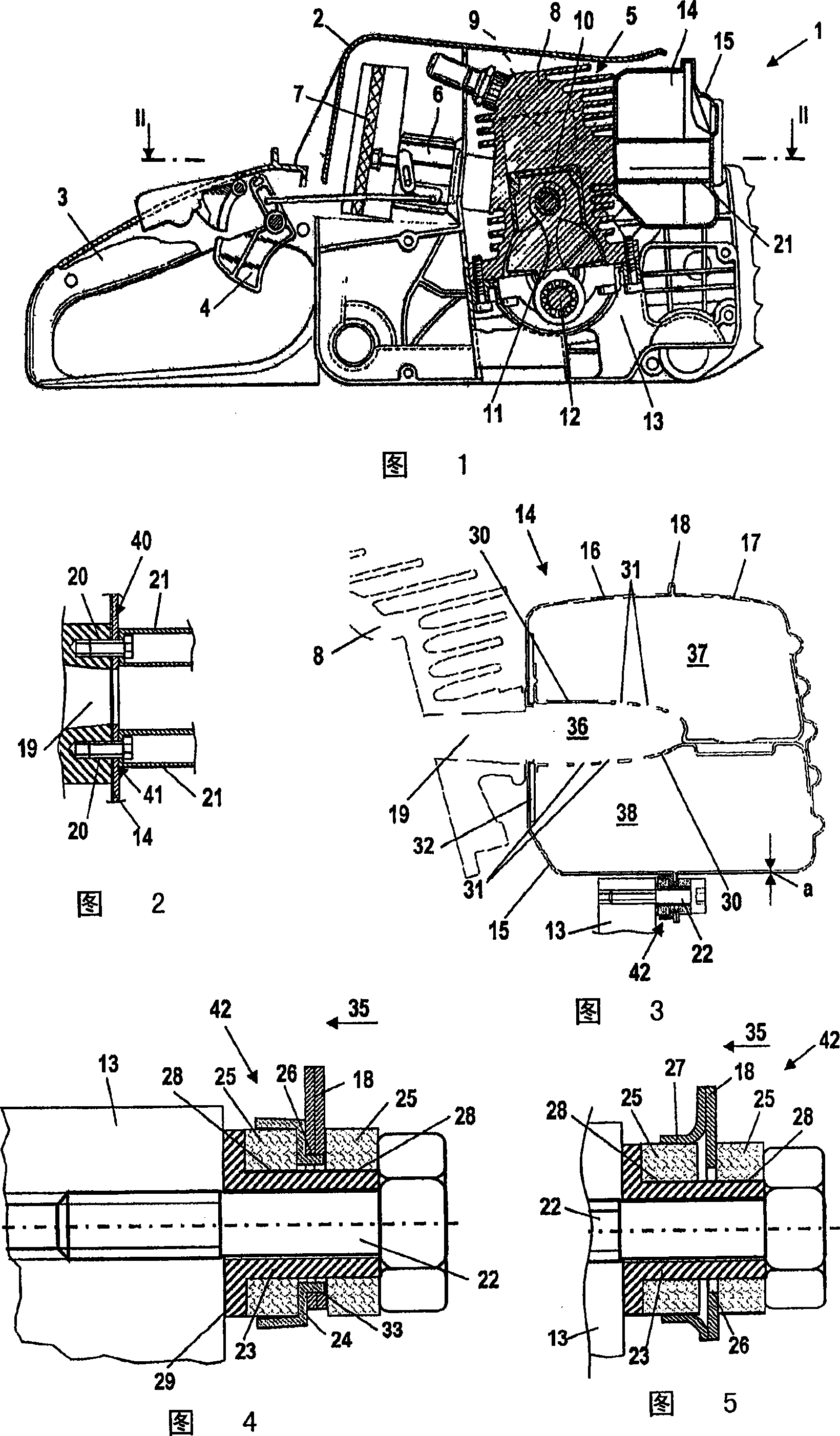
[0020] The work machine shown in FIG. 1 is a power saw 1 . The power saw 1 has a housing 2 on which a rear handle 3 is fastened. The rear handle 3 has a gas lever 4 for operating an internal combustion engine 5 arranged in the housing 2 . The internal combustion engine 5 is a single-cylinder two-stroke engine and contains an air filter 7 which is connected to the internal combustion engine 5 via a carburetor 6 . The intake duct formed in the carburetor 6 opens into the crankcase 13 of the internal combustion engine 5 . The internal combustion engine 5 has a cylinder 8 in which a combustion chamber 9 is formed. A piston 10 is accommodated in the cylinder 8 so as to move back and forth. The piston 10 drives a crankshaft 12 , which is rotatably accommodated in a crankcase 13 , via a connecting rod 11 . The crankshaft 12 drives a tool, not shown in FIG. 1 , ie a saw chain, in rotation. An exhaust muffler 14 with a housing 15 is arranged on the internal combustion engine 5 . ...


PUM


Abstract

A portable handheld work apparatus has an internal combustion engine ( 5 ) having a cylinder ( 8 ) and a crankcase ( 13 ). The cylinder ( 8 ) has an opening ( 19 ) for exhaust gases whereat an exhaust-gas muffler ( 14 ) is mounted. The exhaust-gas muffler ( 14 ) is mounted on the cylinder ( 8 ) at least at one attachment location ( 40, 41 ) and at least a further attachment location ( 42 ) on the internal combustion engine ( 5 ). A reduced weight of the work apparatus and a low mechanical load of the exhaust-gas muffler ( 14 ) can be achieved when the exhaust-gas muffler is fixed at at least one of the attachment locations ( 42 ) via a connection which permits a limited relative movement between the exhaust-gas muffler ( 14 ) and the internal combustion engine ( 5 ) in at least one direction.

Description

technical field [0001] The invention relates to a hand-held (handgeführt) working machine with an internal combustion engine having a cylinder and a crankcase, wherein the cylinder has an outlet for exhaust gases, on which an exhaust muffler is arranged, wherein the exhaust muffler is located on at least one The fastening point is fastened to the cylinder and at least one other fastening point to the internal combustion engine. Background technique [0002] It is known for working machines to use an internal combustion engine with an exhaust muffler for the exhaust gases of the internal combustion engine to drive the tool. It is known from JP 6-248939 that the exhaust muffler is fastened not only to the cylinder, but also to the crankcase of the working machine. The fastening points on the cylinder and on the crankcase are usually relatively far apart from each other. It is also known to fasten the internal combustion engine to the cylinder at another fixed location. [0...

Claims


Application Information

Patent Timeline
Patent Type & Authority Applications(China)
IPC IPC(8): F01N7/18F01N13/18
CPCF01N1/00F01N2590/06F01N13/1888F01N13/002F01N13/1811
Inventor J·门泽尔M·施米德W·韦瑟特E·博纳克
Owner ANDREAS STIHL AG & CO KG
Why Eureka
Try Eureka