Rotating hub type automatic focusing lens

An automatic focusing and hub-rotating technology, which is applied in focusing devices, installation, optics, etc., can solve the problems of small rolling linear guide rail friction resistance, high cam curve processing requirements, low matching accuracy, etc., and achieve low manufacturing and installation process requirements , Meet the requirements of mass production, good optical axis consistency

Pending Publication Date: 2020-10-30
WUCHANG UNIV OF TECH +1
View PDF0 Cites 0 Cited by
  • Summary
  • Abstract
  • Description
  • Claims
  • Application Information

AI Technical Summary

Problems solved by technology

[0002] With the development of optical electromechanical technology, the lens is required to be able to automatically adjust the focus. The traditional focusing methods include: (1) threaded meshing type, the transmission method is simple, but the friction is large and the matching accuracy is low, which cannot be applied to the optical axis consistency requirements. High occasions; (2) Linear focusing type, rolling linear guide rail with small frictional resistance, low driving power, high positioning accuracy and repeat positioning accuracy; the main lens barrel and focusing barrel are closely matched and have a large contact area, so the The frictional resistance is large, and a motor with a large safety factor must be selected to meet the driving requirements; its assembly accuracy is high and cumbersome, which makes mass production difficult; (3) Cam mechanism type, the structure of the cam mechanism is relatively simple, but the processing of the cam curve High requirements, difficult batch production
At the same time, because the limit pin makes a curved movement in the curved groove, the speed is low, and the switching time of the field of view is slightly longer, which cannot meet the requirements of rapidity and mobility.

Method used


Image

  • Rotating hub type automatic focusing lens
  • Rotating hub type automatic focusing lens
  • Rotating hub type automatic focusing lens

Examples


Embodiment Construction

[0031] The principles and features of the present invention are described below in conjunction with the accompanying drawings, and the examples given are only used to explain the present invention, and are not intended to limit the scope of the present invention.

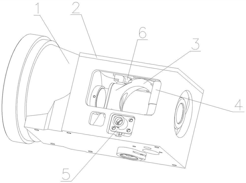
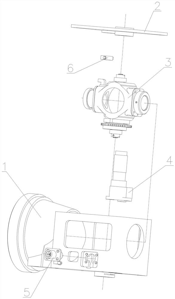
[0032] Such as Figure 1-8 As shown, a hub-type autofocus lens includes a main mirror base 1, an upper cover 2, a hub assembly 3, a motor assembly 4, a field of view positioning assembly 5 and a limit switch 6, and the hub assembly 3 and The motor components 4 are all arranged in the main mirror base 1, the upper cover 2 is fixedly connected to one side of the main mirror base 1, and the limit switch 6 is fixedly connected to the inner side of the upper cover 2, so The motor assembly 4 drives the hub assembly 3 to rotate to 0° or 90°, and the hub assembly 3 is also provided with a trigger device to collide with and trigger the limit switch 6 to stop the motor assembly 4 The field of view positioning assembly 5 is a...


PUM


Abstract

The invention relates to a rotating hub type automatic focusing lens which comprises a main mirror base, an upper cover, a rotating hub assembly, a motor assembly, a view field positioning assembly and a limiting switch. The rotating hub assembly and the motor assembly are both arranged in the main mirror base. The upper cover is fixedly connected to one side of the main lens base. The limiting switch is fixedly connected to the inner side of the upper cover. The motor assembly drives the rotating hub assembly to rotate to the position of 0 degree or 90 degrees. The rotating hub assembly is further provided with a triggering device used for colliding with and triggering the limiting switch to stop the motor assembly. The view field positioning assembly is arranged on one side of the main lens base and used for locking the rotating hub assembly when the rotating hub assembly rotates to the position of 0 degree or 90 degrees. The beneficial effects are that the focusing speed is high andthe optical axis consistency is good. The requirements on manufacturing and mounting processes are low, and the requirement on large-batch production is met. The change of the azimuth direction is realized by only interactively changing between a 0-degree position and a 90-degree position, the switching speed is extremely high, and the requirements of rapidness and maneuverability are met.

Description

technical field [0001] The invention relates to an optical device, in particular to a hub type automatic focusing lens. Background technique [0002] With the development of optical electromechanical technology, the lens is required to be able to automatically adjust the focus. The traditional focusing methods include: (1) threaded meshing type, the transmission method is simple, but the friction is large and the matching accuracy is low, which cannot be applied to the optical axis consistency requirements. High occasions; (2) Linear focusing type, rolling linear guide rail with small frictional resistance, low driving power, high positioning accuracy and repeat positioning accuracy; the main lens barrel and focusing barrel are closely matched and have a large contact area, so the The frictional resistance is large, and a motor with a large safety factor must be selected to meet the driving requirements; its assembly accuracy is high and cumbersome, which makes mass producti...

Claims


Application Information

Patent Timeline
Patent Type & Authority Applications(China)
IPC IPC(8): G02B7/09G03B13/36
CPCG02B7/09G03B13/36
Inventor 费国标彭玉华李强张义
Owner WUCHANG UNIV OF TECH
Why Eureka
Try Eureka