Punching machine

A stamping machine and support leg technology, applied in the field of stamping machines, can solve the problems of wasting electric energy and accelerating the damage of guide plates, etc., and achieve the effects of improving production efficiency, saving electric energy, and reasonable design

Inactive Publication Date: 2014-04-23
KUNSHAN HUAKUI MACHINERY ELECTRONICS
View PDF7 Cites 27 Cited by
  • Summary
  • Abstract
  • Description
  • Claims
  • Application Information

AI Technical Summary

Problems solved by technology

In national production, the stamping process has the advantages of saving materials and energy, high efficiency, low technical requirements for operators, and the ability to produce products that cannot be achieved by mechanical processing through various mold applications. Its use is more and more extensive. According to the stamping die disclosed in the patent CN 202877379 U, although the stamping die has a simple structure, high stamping precision, high stability and reliable operation, the return of the punch after stamping needs to be done by a hydraulic device. Realization, this wastes electric energy, and the stop block used in it does not have a shock absorbing device, which will accelerate the damage of the guide plate, and at the same time, the formed parts after stamping do not have a storage box. In order to solve the above problems, a new technical solution is specially provided

Method used


Image

  • Punching machine

Examples


Embodiment Construction

[0010] In order to make the object, technical solution and advantages of the present invention clearer, the present invention will be further described in detail below in conjunction with the accompanying drawings and embodiments. It should be understood that the specific embodiments described here are only used to explain the present invention, not to limit the present invention.

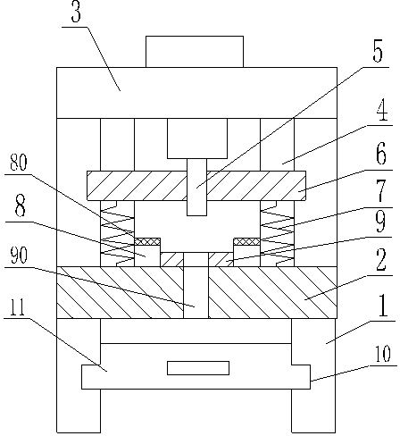
[0011] see figure 1 , figure 1 It is a structural schematic diagram of the present invention.

[0012] A stamping machine, comprising a support leg 1, the upper end of the support leg 1 is provided with a lower die base 2, a guide rod 4 is provided between the lower die base 2 and an upper die base 3, and a guide rod 4 is arranged between the guide rods 4 There is a guide plate 6, a stamping head 5 is arranged in the middle of the guide plate 6, a stop block 8 is provided on the inner side of the guide rod 4, a die 9 is arranged between the stop block 8, and the die 9 and The lower mold base 2 i...


PUM

PropertyMeasurementUnit
thicknessaaaaaaaaaa

Abstract

The invention relates to a punching machine which comprises a supporting leg, wherein a lower die seat is arranged at the upper end of the supporting leg, guide rods are arranged between the lower die seat and an upper die seat, a guide plate is arranged between the guide rods, a punching head is arranged in the middle of the guide plate, stoppage blocks are arranged on the inner sides of the guide rods, a concave die is arranged between the two stoppage blocks, a discharging hole is formed in the concave die and the lower die seat, grooves are formed in the inner side of a supporting seat, a containing box is arranged between the grooves, return springs are arranged in the guide rods and positioned between the guide plate and the lower die seat, and damping layers are arranged at upper ends of the stoppage blocks. The punching machine is simple in structure and reasonable in design. The return springs are arranged between the guide plate and the lower die seat, so that the guide plate can return to the original place automatically after the punching machine punches plates, and electric energy is saved. Furthermore, due to the fact that the damping layers are arranged on the stoppage blocks, impact force to the guide plate and the stoppage blocks is effectively retarded, and the guide plate is protected.

Description

technical field [0001] The invention relates to the mechanical field, in particular to a stamping machine. Background technique [0002] A punch press is a stamping press. In national production, the stamping process has the advantages of saving materials and energy, high efficiency, low technical requirements for operators, and the ability to produce products that cannot be achieved by mechanical processing through various mold applications. Its use is more and more extensive. According to the stamping die announced in the patent CN 202877379 U, although the stamping die has a simple structure, high stamping precision, high stability and reliable operation, the return of the punch after stamping needs to be done by a hydraulic device. Realization, this wastes electric energy, and the stop block used in it does not have a shock absorbing device, which will accelerate the damage of the guide plate, and at the same time, the formed parts after stamping do not have a storage b...

Claims


Application Information

Patent Timeline
Patent Type & Authority Applications(China)
IPC IPC(8): B21D22/02B21D37/10B21D45/00B30B15/00B30B15/02B30B15/32
Inventor 严凤良
Owner KUNSHAN HUAKUI MACHINERY ELECTRONICS
Why Eureka
Try Eureka