Stroke reflection horizontal joint multi-head adjustable screw locking machine

A horizontal joint and screw technology, which is applied in the field of stroke displacement horizontal joint multi-head adjustable screw locking machines, can solve the problems of increased labor cost, low production efficiency, and reduced enterprise production efficiency.

Active Publication Date: 2014-04-23
DONGGUAN OKATA ELECTRONICS & TECH
View PDF5 Cites 16 Cited by
  • Summary
  • Abstract
  • Description
  • Claims
  • Application Information

AI Technical Summary

Problems solved by technology

[0002] The existing screw conveying is mainly through the radial conveying of the plastic hose. Before the screw enters the plastic hose, the screw is manually screwed. The manual operation is time-consuming, labor-intensive, low in production efficiency, and high in labor costs. It is not suitable for modern large-scale scale industrial production
Moreover, the existing screw retrieving mechanisms are all fixedly installed, and the positions of screw loading and tightening are fixed, and cannot be adjusted according to the needs of production, and cannot be rotated. If they are not in the same position, or need to install screws of different lengths, sizes, and sizes, they must wait until the screws of the same model and position are installed, and then change to another batch of screws of the same model and the same position to continue the installation. The efficiency of screw retrieving is low, and the efficiency of screw loading and tightening is low
When the existing retrieving mechanism changes the fixing position of the screw, since the retrieving mechanism is set at a fixed position, it cannot be adjusted or rotated, and the object to be screwed needs to be manually moved, which greatly reduces the production efficiency of the enterprise and increases the Expenditure on labor costs is difficult to meet the high requirements of today's industrial development and product diversification

Method used


Image

  • Stroke reflection horizontal joint multi-head adjustable screw locking machine

Examples


Embodiment Construction

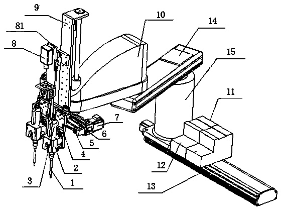
[0013] In this example, refer to figure 1 As shown, a stroke displacement horizontal joint multi-head adjustable screw locking machine of the present invention includes a suction nozzle 1, a buffer mechanism 2 arranged on the suction nozzle 1, and an electric batch 3 arranged on the buffer mechanism 2, And be arranged on the connecting plate 4 behind the buffer mechanism 2, and be arranged on the lateral displacement mechanism 5 behind the connecting plate 4, and be arranged on the lateral sliding mechanism 6 above the lateral displacement mechanism 5, and be arranged on the displacement behind the left end of the lateral displacement mechanism 5 Motor 7, and the visual positioning image device 8 arranged on the top of the lateral displacement mechanism 5, and the visual positioning image mounting plate 81 arranged behind the visual positioning image device 8, and the mounting frame 9 arranged behind the visual positioning image mounting plate 81, And the horizontal joint robo...


PUM


Abstract

The invention relates to a stroke reflection horizontal joint multi-head adjustable screw locking machine which comprises a suction nozzle, a buffering mechanism arranged on the suction nozzle, an electric screwdriver arranged on the buffering mechanism, a connection plate arranged behind the buffering mechanism, a transverse displacement mechanism arranged behind the connection plate, a transverse sliding mechanism arranged on the transverse displacement mechanism, a displacement motor arranged behind the left end of the transverse displacement mechanism, a vision location image device is arranged above the transverse displacement mechanism, a vision location image installation plate is arranged behind the vision location image device, an installation support arranged behind the vision location image installation plate, a horizontal joint robot arranged behind the installation support, a screw feeder arranged on the left side of the horizontal joint robot and a screw feeding location hole formed in front of the screw feeder. The suction nozzle and the electric screwdriver are arranged in a multi-position mode and can rotate through 360 degrees. The screw locking machine is good in effect and high in efficiency by combining vision accurate location.

Description

technical field [0001] The present invention relates to a screw locking machine, in particular to a kind of stroke displacement horizontal joint multi-head adjustable which can carry out 360-degree rotation suction through visual precise positioning, and automatically complete screw feeding, nailing and tightening. Screw locking machine. Background technique [0002] The existing screw conveying is mainly through the radial conveying of the plastic hose. Before the screw enters the plastic hose, the screw is manually screwed. The manual operation is time-consuming, labor-intensive, low in production efficiency, and high in labor costs. It is not suitable for modern large-scale large-scale industrial production. Moreover, the existing screw retrieving mechanisms are all fixedly installed, and the positions of screw loading and tightening are fixed, and cannot be adjusted according to the needs of production, and cannot be rotated. If they are not in the same position, or ne...

Claims


Application Information

Patent Timeline
Patent Type & Authority Applications(China)
IPC IPC(8): B23P19/06
CPCB23P19/001B23P19/006B23P19/069
Inventor 吴水鱼田卫兵
Owner DONGGUAN OKATA ELECTRONICS & TECH
Why Eureka
Try Eureka