
Wear-resistant halving stick for mould processing

A technology for mold processing and centring rods, applied in metal processing equipment, metal processing mechanical parts, manufacturing tools, etc., can solve the problems of easy wear, reduced service life, easy to be magnetized, etc., to achieve long service life, simple structure, Guarantee the effect of normal use

Inactive Publication Date: 2014-04-23
中山市利群精密实业有限公司
View PDF9 Cites 0 Cited by
  • Summary
  • Abstract
  • Description
  • Claims
  • Application Information

AI Technical Summary

Problems solved by technology

[0002] The existing centering rods are generally made of steel materials, which are relatively easy to wear and magnetized during use, thereby reducing its service life

Method used


Image

  • Wear-resistant halving stick for mould processing

Examples


Embodiment Construction

[0012] The present invention will be further described below in conjunction with accompanying drawing description and specific embodiment:

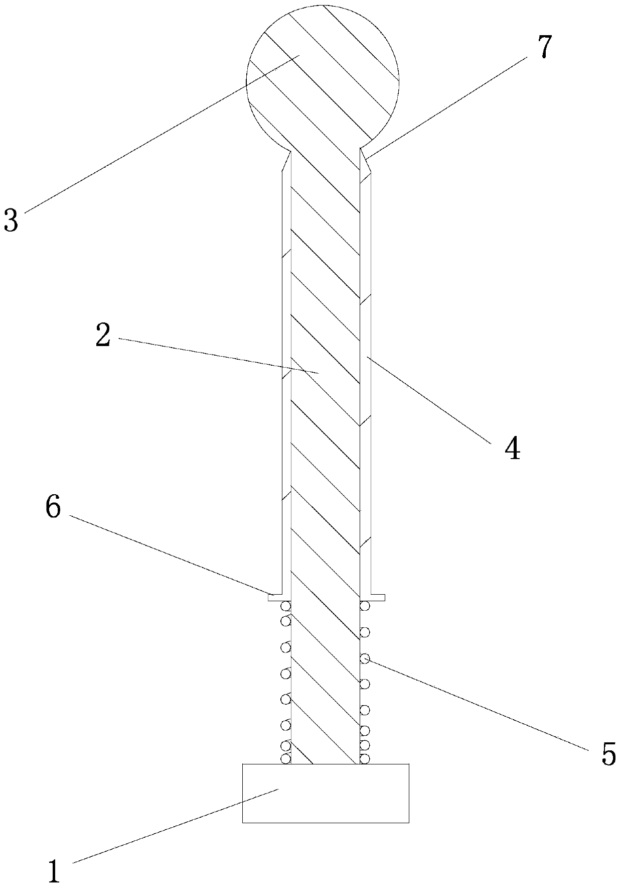
[0013] Such as figure 1 The shown wear-resistant centering rod for mold processing includes a rod end 1, a rod body 2 is arranged on the rod end 1, and a steel ball 3 is arranged on the end of the rod body 2, A ceramic sleeve 4 is sheathed on the outer side of the rod body 2 , and a pressing spring 5 capable of pressing the ceramic sleeve 4 against the steel ball 3 is provided between the ceramic sleeve 4 and the rod end 1 .

[0014] In the present invention, a position-limiting protruding ring 6 is provided at the lower end of the ceramic sleeve 4, one end of the pressing spring 5 presses on the position-limiting protruding ring 6, and the other end of the pressing spring 5 presses on the rod end 1 .

[0015] The diameter of the steel ball 3 in the present invention is 2mm. A tapered surface 7 is provided on the outer wall of the uppe...


PUM

PropertyMeasurementUnit
diameteraaaaaaaaaa

Abstract

The invention discloses a wear-resistant halving stick for mould processing. The wear-resistant halving stick is characterized by comprising a stick end, wherein the stick end is provided with a stick body, a steel ball is arranged at one end of the stick body, a ceramic sleeve is sleeved outside the stick body, and a jacking spring capable of jacking the ceramic sleeve on the steel ball is arranged between the ceramic sleeve and the stick end. The wear-resistant halving stick for the mould processing with simple structure aims to overcome defects in the prior art.

Description

technical field [0001] The invention relates to a wear-resistant centering rod used for mold processing. Background technique [0002] Existing centering rods are generally made of steel materials, which are relatively easy to wear and magnetized during use, thereby reducing their service life. Contents of the invention [0003] The purpose of the present invention is to overcome the disadvantages of the prior art, and provide a wear-resistant centering rod with simple structure and wear resistance for mold processing. [0004] In order to achieve the above object, the present invention adopts the following scheme: [0005] A wear-resistant centering rod for mold processing, characterized in that it includes a rod end, a rod body is provided on the rod end, steel balls are arranged on the rod body end, and a rod body is arranged on the rod end. A ceramic sleeve is sheathed on the outside of the body, and a pressing spring capable of pressing the ceramic sleeve against th...

Claims


Application Information

Patent Timeline
Patent Type & Authority Applications(China)
IPC IPC(8): B23Q17/22
CPCB23Q17/22
Inventor 童章狄
Owner 中山市利群精密实业有限公司
Learn More