Pneumatic reversing solenoid valve

A reversing solenoid valve and pneumatic technology, applied in the field of solenoid valves, can solve problems such as failure to guarantee the normal operation of the solenoid valve, failure of the solenoid valve to work normally, loss of electromagnetic suction, etc., to achieve no magnetic residue, avoid outward injection, and improve utilization rate effect

Inactive Publication Date: 2015-01-07
NINGBO HANDSUN AUTOMATION IND
View PDF7 Cites 3 Cited by
  • Summary
  • Abstract
  • Description
  • Claims
  • Application Information

AI Technical Summary

Problems solved by technology

[0002] In the pneumatic industry, in view of the long-term uninterrupted work of the solenoid valve and the relatively high frequency of action (more than 3 times per second), the service life of the domestically produced pneumatic reversing solenoid valve is relatively short, generally no more than half a year, half a year Finally, it is impossible to guarantee that each solenoid valve can work normally. After analysis, it mainly has the following defects: First, after the coil is matched with the pilot assembly, because the length of the pilot assembly is longer than the height of the coil, each of the moving iron core and the static iron core One end is respectively higher than the two ends of the coil, and correspondingly higher than the iron bracket inside the coil. The magnetic field lines generated after the coil is energized will be shot out through the higher moving iron core and static iron core, resulting in the loss of electromagnetic attraction. Therefore, the current market The power of the upper coil is greater than 4w; second, the market requirement is to work uninterruptedly for a long time and the action frequency is relatively high (more than 3 times per second), that is, when the coil works uninterruptedly for a long time, it will not stop when the power is turned on and off. Stop switching, and the switching frequency is more than 3 times per second. During this process, the outward injection and stop of the magnetic force lines are also constantly switching. At the moment when the coil is powered off, every time there is a small amount of magnetic force lines left in the pilot assembly. At both ends, through the accumulation of a certain period of time, the moving iron core and the static iron core are magnetized, so that the entire solenoid valve cannot work normally.

Method used


Image

  • Pneumatic reversing solenoid valve

Examples


Embodiment Construction

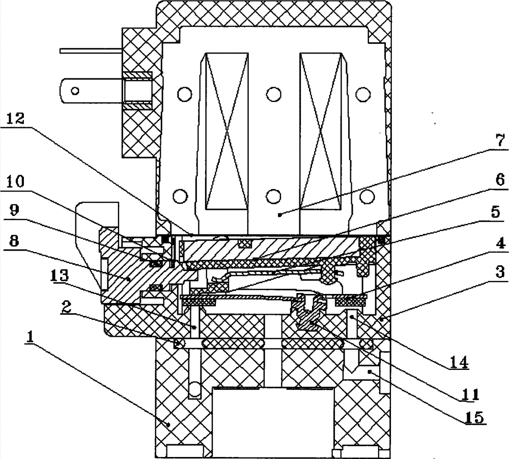
[0012] Such as figure 1 As shown, a pneumatic reversing solenoid valve includes a pilot valve seat 1, a pilot valve seat 3, a coil 7, a moving iron core 6 and a sealing support 4, and the coil 7 is provided with a static iron core, which is composed of Silicon steel sheets are stacked, the static iron core includes 5-8 silicon steel sheets, the silicon steel sheets are in the shape of a mountain, the moving iron core 6 is located directly below the coil 7, the moving iron core 6 and the coil 7 A sealing sheet 12 is connected between them, the moving iron core 6 is rectangular, and the moving iron core 6 is covered with a rubber layer. The valve seat 3 is connected, and the bottom of the pilot valve seat 3 has a through hole. The left side of the through hole is opened with an air intake channel 13, and the right side is opened with an exhaust channel 14. The air intake channel 13 is connected to one end of the sealing bracket 4. Matching, the exhaust channel 14 is matched wit...


PUM


Abstract

The invention relates to a pneumatic reversing solenoid valve comprising a guide seat, a pilot seat, a coil, a movable iron core and an enclosing support. A static iron core is arranged in the coil and is composed of stacked silicon steel sheets; the movable iron core is arranged under the coil and is connected to the enclosing support through a spring sheet; the enclosing support is connected to the pilot seat through an embedding member; the bottom of the pilot seat is connected to the guide seat. By means of the combination of the silicon steel sheets and the movable iron core, all the magnetic flux produced by energizing the coil is arranged in an enclosed annular iron ring, the utilization rate of the energy of the electromagnetic field is increased, the power of the novel coil can be of 2W, and the effect of energy saving can be implemented; in addition, the enclosed annular magnetic field is formed, the magnetic flux is prevented from emitting outwardly, magnetic residue is eliminated, the silicon steel sheets and the movable iron core are prevented from being magnetized, long-term uninterrupted high-frequency operation can be implemented, and the service life can be prolonged by 2 to 6 times.

Description

technical field [0001] The invention relates to a solenoid valve, in particular to a pneumatic reversing solenoid valve. Background technique [0002] In the pneumatic industry, in view of the long-term uninterrupted work of the solenoid valve and the relatively high frequency of action (more than 3 times per second), the service life of the domestically produced pneumatic reversing solenoid valve is relatively short, generally no more than half a year, half a year Finally, it is impossible to guarantee that each solenoid valve can work normally. After analysis, it mainly has the following defects: First, after the coil is matched with the pilot assembly, because the length of the pilot assembly is longer than the height of the coil, each of the moving iron core and the static iron core One end is respectively higher than the two ends of the coil, and correspondingly higher than the iron bracket inside the coil. The magnetic field lines generated after the coil is energized ...

Claims


Application Information

Patent Timeline
Patent Type & Authority Applications(China)
IPC IPC(8): F16K31/06F16K1/00
CPCF16K31/0655F16K31/0675F16K31/10F16K31/60
Inventor 毛旭东
Owner NINGBO HANDSUN AUTOMATION IND
Why Eureka
Try Eureka