

Automatic membrane change device of automatic filling binding machine
An automatic filling and automatic film changing technology, which is applied in the direction of packaging material feeding device, packaging, transportation packaging, etc., can solve the problems of abnormal film conveying, affecting production efficiency, unqualified packaging, etc., and achieves simple loading and unloading, easy debugging, Ease of use
- Summary
- Abstract
- Description
- Claims
- Application Information
AI Technical Summary
Problems solved by technology
Method used
Image


Examples
Embodiment Construction
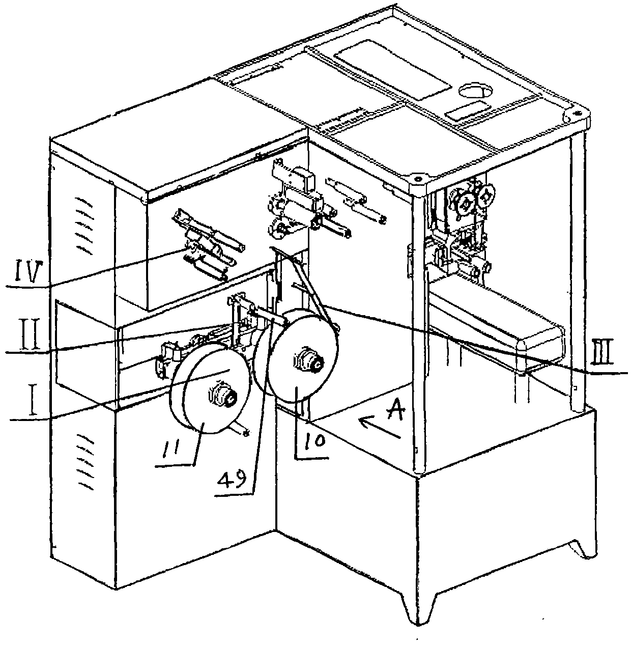
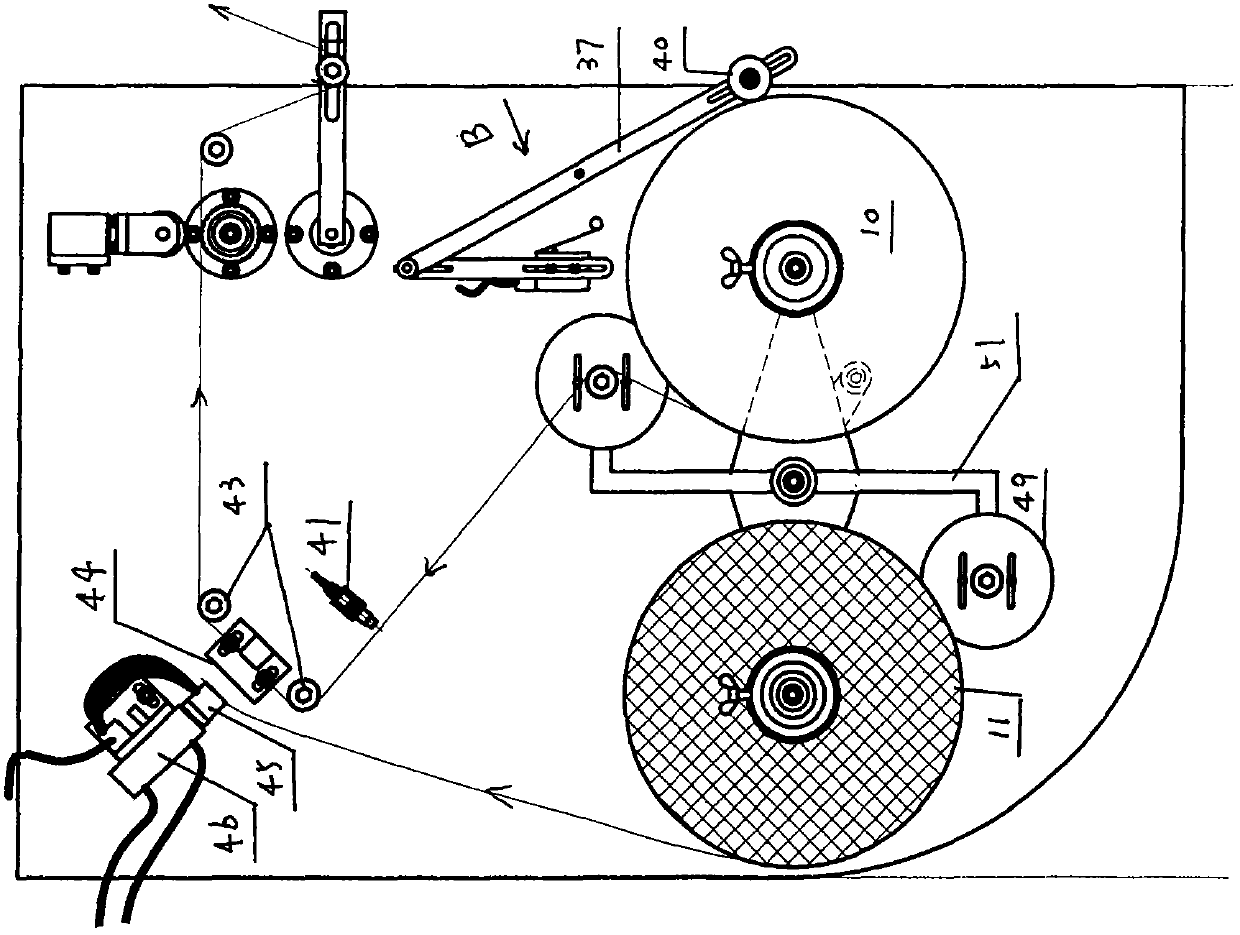
[0023] Further detailed explanation in conjunction with accompanying drawing, figure 2 The arrow in shows the direction of membrane transmission;
[0024] Such as Figure 1~6 Shown, the structure of the film changing roll device 1 is that the changing roll shaft 1 bearing type of the power input gear 2 is installed on two main bearing blocks 3 fixedly mounted on the flat frame plate 14, and one end of the changing roll shaft 1 faces After crossing the functional hole on the vertical plate 15 and installing the shaft sleeve 5, the detachable fixed shift fork 6 is fixed on the shaft end, and the connecting plate 7 is fixed on the shaft sleeve 5, and the two ends of the connecting plate 7 are symmetrical. The mandrel 8 with a large drum 9 is fixedly installed in each formula. The film roll 10 and the spare film roll 11 are respectively detachably mounted on the large drum 9. The connecting plate 7 is also detachably fixed with In the film guide mechanism that is synchronously ...
PUM
 Abstract
Description
Claims
Application Information