
Lead wire looping machine

A looping machine and wire technology, applied in the direction of conveying filamentous materials, thin material processing, transportation and packaging, etc., can solve the problems of wasting labor, low production efficiency, and restricting the development of enterprises, so as to promote the degree of automation and improve Productivity and versatility-enhancing effect

Inactive Publication Date: 2014-04-23
SHANGHAI UNIV
View PDF6 Cites 11 Cited by
  • Summary
  • Abstract
  • Description
  • Claims
  • Application Information

AI Technical Summary

Problems solved by technology

At present, many of the wires are still in a purely manual state, which not only wastes labor, but also has low production efficiency, which restricts the development of enterprises to a certain extent.

Method used


Image

  • Lead wire looping machine
  • Lead wire looping machine
  • Lead wire looping machine

Examples


Embodiment 1

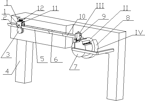
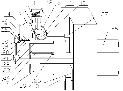
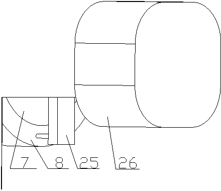
[0029] In this example, see Figure 1 to Figure 8 , the wire looping machine, comprising a frame 4 equipped with wire feeding device I, winding device II, tape wrapping device III and wire pushing device IV, wire feeding device I is installed on the front end of frame 4, winding device II Installed on the rear end of the frame 4, the output end of the wire feeding guide rail in the wire feeding device I is connected to a reel 7 in the winding device II; the tape wrapping device III is installed on one side of the winding device II, so that A tape winding mechanism 9 in the tape winding device III moves up and down with the reel 7 as the midpoint; a wire pushing device IV is installed on the other side of the winding device II, so that one of the wire pushing devices IV is placed on the reel 7 The push wire ring 8 moves back and forth along the axis of the reel.

Embodiment 2

[0031] In this example, see Figure 1 to Figure 8 , a wire looping machine, mainly composed of a frame 4, a wire feeding device, a wire winding device, a tape wrapping device and a wire pushing device, the wire feeding device includes a front fixed guide rail 2, a middle fixed guide rail 5, a rear fixed guide rail 6, The movable guide rail 10, the driving guide wheel 3 and the driven guide wheel 1, the front fixed guide rail 2, the middle fixed guide rail 5 and the rear fixed guide rail 6 are connected in series in a straight line and fixedly connected with the frame 4, and the movable guide rail 10 and the cylinder 27 The piston rod ends are fixedly connected, the cylinder 27 is fixed on the frame 4, the driving guide wheel 3 is connected with the motor in the frame 4 cabinet, and the driven guide wheel 1 is elastically connected with the frame 4 through the spring 12; the winding device includes a motor Component 26, reel 7 and wire crimping rod set, reel 7 is connected with...


PUM


Abstract

The invention discloses a lead wire looping machine. The lead wire looping machine comprises a machine rack, a wire feeding device, a wire winding device, an adhesive tape winding device and a wire pushing device. The wire feeding device consists of a fixed guide rail, a movable guide rail, a driving guide wheel and a driven guide wheel, wherein the movable guide rail is fixedly connected with an air cylinder, the driving guide wheel is connected with a motor in a machine rack case, and the driven guide wheel is connected with the machine rack through a spring. The wire winding device consists of a motor, a winding drum and a wire pressing rod external member, wherein the motor controls rotation of the winding drum, and a control system controls pressing of a wire pressing rod and release of the lead wire end. The adhesive tape winding device consists of an adhesive tape winding assembly and two air cylinders, wherein one air cylinder controls horizontal motion of the adhesive tape winding assembly and finishes adhesive tape winding, the other air cylinder control vertical separation of the adhesive tape winding assembly and achieves the purpose of passing in and out of a winding drum groove. The wire pushing device consists of a wire pushing ring and an air cylinder, wherein the air cylinder pushes the wire pushing ring to push a looped lead wire away from the winding drum. Lead wire looping can be effectively finished by adopting the reasonable structural design.

Description

technical field [0001] The invention relates to a wire finishing device, in particular to a wire looping machine, which is used in factories to wind wires into loops. Background technique [0002] With the development of industrial technology, many production lines have been automated, including fully automatic and semi-automatic modes. At present, many wires are still in a purely manual state, which not only wastes labor, but also has low production efficiency, which restricts the development of enterprises to a certain extent. Therefore, it is very necessary to realize the automation of wire winding. Contents of the invention [0003] The object of the present invention is to overcome the deficiencies of the prior art, and provide a wire looping machine, which can effectively ensure the completion of wire looping by using its automatic wire feeding, looping, and tape wrapping. [0004] To achieve the above object, the inventive concept is: [0005] A wire looping mach...

Claims


Application Information

Patent Timeline
Patent Type & Authority Applications(China)
IPC IPC(8): B65H54/22B65H54/70B65H54/74B65H51/08B65H81/02
Inventor 刘吉成华凌云周晓君李斌崔建祥卢熙昌
Owner SHANGHAI UNIV
Learn More