Oil vapor recovery atomizer

An atomizer, oil and gas technology, applied in special distribution devices, packaging, distribution devices, etc., to increase the effect of oil and gas recovery and prevent the effect of life reduction

Active Publication Date: 2014-04-23
FUJIAN DONGFANG RUIER MACHINE MFG CO LTD
View PDF5 Cites 1 Cited by
  • Summary
  • Abstract
  • Description
  • Claims
  • Application Information

AI Technical Summary

Problems solved by technology

[0004] The technical problem to be solved by the present invention is to provide an oil gas recovery atomizer for the above-mentioned deficiencies in the prior art, which can atomize a small amount of oil, so that it can be recycled, and the recovery effect is better; At the same time, it can effectively prevent the oil from being sucked into the vacuum pump, and prevent the life of the vacuum pump from being reduced or even damaged due to the oil entering.

Method used


Image

  • Oil vapor recovery atomizer
  • Oil vapor recovery atomizer

Examples


Embodiment 1

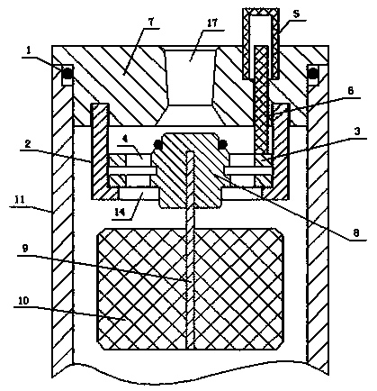
[0018] Embodiment one: if figure 1 As shown, an atomizer for oil and gas recovery includes an atomizer body 11, the upper and lower ends of the atomizer body 11 are respectively provided with an upper end cap 7 and a lower end cap 12, and the upper end cap 7 and the lower end cap 12 are connected to the A sealing ring 1 is provided between the atomizer bodies 11, and an oil and gas outlet 17 communicating with the interior of the atomizer body 11 is provided on the upper end cap 7, and the interior of the atomizer body 11 is close to the upper end cap 7, a valve cavity corresponding to the oil and gas outlet 17 is provided, and a valve core 8 corresponding to the oil and gas outlet 17 is arranged in the valve cavity, and the side wall of the valve core 8 is provided with a valve cavity matching the above valve cavity, and The valve plate 3 that can slide up and down in the valve cavity, the valve plate 3 is provided with a plurality of oil and gas through holes 4, and the bott...

Embodiment 2

[0024] Embodiment two: if figure 2 As shown, the lower end surface of the upper end cover 7 is provided with a thread groove, the valve cavity is formed by the valve core end cover 2 threaded on the thread groove, and the valve hole 14 is directly arranged at the valve core end On the cover 2, the rest of the structure of this embodiment is the same as that of Embodiment 1.

[0025] The valve cavity of the present invention can be realized through various structures and combinations, as long as it can complete the required functions, it is not limited to the structures disclosed in the above embodiments, such as the valve cavity can also be integrally formed on the upper end The lower end surface of the cover 7 or the valve core end cover 2 of the inner wall of the atomizer body 11 is formed, and the valve hole 14 is directly arranged on the valve core end cover 2 .

[0026] The present invention can not only atomize a small amount of oil that enters the atomizer, but recycl...


PUM


Abstract

The invention discloses an oil vapor recovery atomizer comprising an atomizer body. An upper end cover and a lower end cover are arranged at the upper end and the lower end of the atomizer body, an oil gas outlet communicated with the inner portion of the atomizer body is arranged on the upper end cover, a valve cavity corresponding to the oil gas outlet is arranged at a position of the inner portion of the atomizer body closing to the upper end cover, a valve element corresponding to the oil gas outlet is arranged in the valve cavity, valve blocks matched with the valve cavity and capable of sliding up and down in the valve cavity is arranged on the side wall of the valve element, a plurality of oil gas through holes are arranged on the valve blocks, the lower portion of the valve blocks is connected with a floating block. A slight of oil liquid entering the atomizer can be atomized and then recovered, oil gas recovery effect can be improved, and large amount of oil liquid can be stopped in the inner portion of the atomizer to prevent vacuum pumps from being damaged or short in service life.

Description

technical field [0001] The invention belongs to the field of oil and gas recovery systems, and in particular relates to an oil and gas recovery atomizer. Background technique [0002] In all gas stations in cities and villages, during the refueling process, as the oil level rises, a large amount of oil and gas will be discharged into the air; vent into the air. The oil and gas discharged into the air is not only a waste of energy, but also pollutes the environment, and because it is a flammable and explosive gas, it also poses a huge safety hazard. Therefore, the recovery of oil and gas is not only effective in saving Energy, reducing air pollution, and greatly reducing the safety hazards of gas stations, making the operation process of refueling safer. [0003] The current oil and gas recovery system basically uses the oil and gas recovery vacuum pump to carry out negative pressure suction on oil and gas. Once the oil is sucked up, once the oil enters the vacuum pump, it...

Claims


Application Information

Patent Timeline
IPC IPC(8): B67D7/32
Inventor 杨江山林亮汤雄肖英
Owner FUJIAN DONGFANG RUIER MACHINE MFG CO LTD
Why Eureka
Try Eureka