
Catalytic combustion treatment device and treatment method for organic waste gases

A catalytic combustion and organic waste gas technology, applied in the direction of combustion method, combustion type, incinerator, etc., can solve the problems of affecting the service life of the catalyst, troublesome manufacturing and processing, and increasing investment costs, so as to improve the comprehensive utilization effect and avoid life reduction. The effect of reducing operating costs

Inactive Publication Date: 2013-04-17
CHINA PETROLEUM & CHEM CORP +1
View PDF7 Cites 7 Cited by
  • Summary
  • Abstract
  • Description
  • Claims
  • Application Information

AI Technical Summary

Problems solved by technology

[0003] CN2590648Y provides a catalytic combustion device for purifying organic waste gas, which is composed of a shell, an air intake cover, an exhaust port, a double-layer fin heat exchanger, several sets of electric heating tubes and several catalytic layers, among which Electric heating tubes and catalytic layers are compounded and interlaced, so they have strong adaptability to changes in exhaust gas volume and exhaust gas concentration, but the structure is more complicated, and the manufacturing process is more troublesome; , high-activity catalyst reaction zone and guaranteed reaction zone, among which the high-activity catalyst reaction zone and the guaranteed reaction zone are both equipped with catalysts. By setting up two reaction zones, it can ensure that the exhaust gas volume fluctuates greatly or the toxic and harmful substances in the exhaust gas Stable up-to-standard discharge of exhaust gas when the concentration fluctuates violently
Although this technology can finally realize the harmless treatment of waste gas, in order to concentrate the low-concentration waste gas and meet the intake concentration requirements of the catalytic combustion device, an adsorption device is installed, which will increase the investment cost and make the process more complicated.
[0004] The above device also has a disadvantage: the active components of the catalytic combustion catalyst are generally noble metals, such as platinum, palladium, etc., and the high temperature environment will affect the service life of the catalyst. When designing the catalytic combustion device, it needs to be designed according to the maximum exhaust gas flow. To ensure that the required purification effect is achieved at the maximum exhaust gas flow
Therefore, when the concentration of organic substances in the exhaust gas is at a low level for a long time, or the amount of exhaust gas is at a low flow rate for a long time, even if only part of the catalyst bed participates in the catalytic combustion reaction of the exhaust gas (the purification effect has been achieved), the high temperature after the reaction The purified gas will also pass through all the catalyst beds that do not participate in the catalytic combustion reaction, thereby shortening the service life of the catalyst

Method used


Image

  • Catalytic combustion treatment device and treatment method for organic waste gases

Examples


Embodiment approach

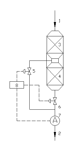
[0019] Such as figure 1 As shown, the organic waste gas catalytic combustion treatment device of the present invention is composed of two catalyst beds A and B connected in series, regulating valves A and B, control system 8, waste gas online analysis equipment 7 and connecting pipelines. When the concentration of the target gas in the exhaust gas entering the device or the amount of treated gas is low, the concentration of the target gas in the main exhaust pipeline 2 is at a low level due to sufficient reaction, that is, it is below the set value. At this time, the control system opens the regulating valve 5 , while closing the regulating valve 6, only the catalyst bed A participates in the catalytic combustion reaction of the exhaust gas; when the concentration of the target gas in the intake line increases or the amount of exhaust gas increases, the reaction of the exhaust gas in the catalyst bed A is insufficient, resulting in the main The concentration of the target gas...

Embodiment

[0022] The organic waste gas discharged from the grease trap, flotation tank and oily sewage tank of a sewage treatment plant is treated by a catalytic combustion device. Under normal operating conditions, the concentration of non-methane total hydrocarbons in the exhaust gas discharged from grease traps, flotation tanks and oily sewage tanks is 2000-5000mg / Nm 3 , but during the large breathing period of the oily sewage tank, the concentration of non-methane total hydrocarbons in the mixed exhaust gas is 4000-8000mg / Nm 3 . Main operating conditions: The whole device is composed of two catalyst beds. Under normal operating conditions, the exhaust gas passes through one bed. During the large breathing period of the oily sewage tank, the exhaust gas passes through the two catalyst beds. The temperature of the exhaust gas entering the catalyst bed is 350°C. Reaction space velocity 8000h -1 .

[0023] After treatment, the concentration of non-methane total hydrocarbons in the pu...


PUM


Abstract

The invention relates to a catalytic combustion treatment device and treatment method for organic waste gases. At least two serially connected catalyst bed layers are provided, each bed layer is connected to a main exhaust pipeline through an exhaust pipeline, and a waste gas on-line analysis device is arranged on the main exhaust pipeline and automatically monitors the target gas concentration on the main exhaust pipeline. When the target gas concentration monitoring value is lower than a set value, only one catalyst bed layer participates in the catalytic combustion reaction through a control regulating valve in the system; and when the target gas concentration monitoring value exceeds the set value, the two catalyst bed layers participate in the catalytic combustion reaction simultaneously through the control regulating valve in the system. Therefore, the device is particularly suitable for stable standard treatment for organic waste gases with large target gas concentration fluctuation, simultaneously, the service life of catalysts can be maximized, and operating costs can be saved maximally.

Description

technical field [0001] The invention provides an organic waste gas catalytic combustion treatment device and treatment method, which belong to the technical field of environmental protection, and are especially suitable for the stable and up-to-standard treatment of organic waste gas with large fluctuations in the amount of waste gas and the concentration of target gas in the waste gas. Background technique [0002] All kinds of industrial production, such as metal printing, insulating materials, enameled wire, coking, paint and chemical industries, produce a large amount of waste gas containing toxic and harmful substances. In addition, industrial or domestic sewage treatment plants are affected by physical, chemical or biological factors. , Wastewater often volatilizes a large amount of organic waste gas during the treatment process, especially in wastewater pretreatment facilities such as homogeneous tanks, buffer tanks, flotation tanks, grease traps and acidification tank...

Claims


Application Information

Patent Timeline
IPC IPC(8): F23G7/07
Inventor 王明星张龙齐慧敏王海波刘忠生
Owner CHINA PETROLEUM & CHEM CORP
Learn More