

Ball valve
A ball valve and valve body technology, applied in the direction of valve devices, cocks including cut-off devices, engine components, etc., can solve the problems of assembly difficulty and complex ball valve structure, and achieve the effect of easy assembly.
- Summary
- Abstract
- Description
- Claims
- Application Information
AI Technical Summary
Problems solved by technology
Method used
Image

Examples
Embodiment Construction
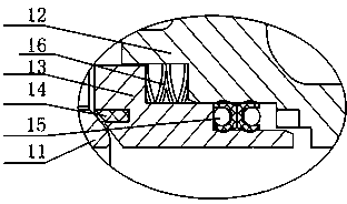
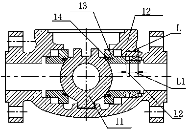
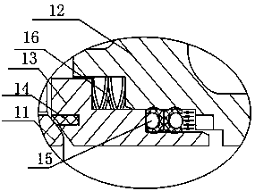
[0029] The ball valve provided by the invention, such as Figure 5 , 6 , 7, 8, including a retainer 53 located between the valve ball 51 and the valve body 52, the retainer 53 and the valve body 52 are sealed and connected by a seal 54, and the valve ball 51 is sealed with the retainer 53; also includes The limiting member 55 is sleeved on the fixture 53, and the limiting member 55 is connected to the valve body 52 for anti-rotation; a sealing member 54 is arranged between the radial end surface of the limiting member 55 and the radially inner end surface of the valve body 52, An elastic member 56 is arranged between the stopper 55 and the radial end face of the fixer 53; a number of second grooves 553 are formed on the end face 552 of the stopper 55 facing the fixer 53, and the fixer 53 matches the second groove 553 There are several protrusions 531 formed at the position; in the assembly position, the protrusions 531 are inserted into the second groove 553; in the working p...
PUM
 Abstract
Description
Claims
Application Information