Can remotely control electronic perpetual calendar equipment

A remote control and perpetual calendar technology, applied in the field of electronic information, can solve the problems that cannot satisfy people and the function of electronic perpetual calendar is too simple

Active Publication Date: 2016-04-06
徐州迅达网络科技有限公司
View PDF6 Cites 0 Cited by
  • Summary
  • Abstract
  • Description
  • Claims
  • Application Information

AI Technical Summary

Problems solved by technology

[0006] However, the electronic perpetual calendar of the prior art can only operate the buttons or other operating elements on the electronic perpetual calendar device to perform settings, such as time settings; in addition, the electronic perpetual calendar of the prior art is still too simple to meet people's needs.

Method used


Image

  • Can remotely control electronic perpetual calendar equipment

Examples


no. 1 example

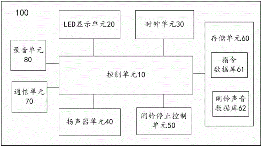
[0052] figure 1 It schematically shows a functional block diagram of a remote control electronic perpetual calendar device according to a preferred embodiment of the present invention.

[0053] Specifically, as figure 1 As shown, the remote-controllable electronic perpetual calendar device 100 according to the preferred embodiment of the present invention includes: a control unit 10 , an LED display unit 20 and a clock unit 30 .

[0054] The clock unit 30 is used for timing and provides time information to the control unit 10 .

[0055] The control unit 10 controls the display of the LED display unit 20 according to time information supplied from the clock unit 30 .

[0056] And, if figure 1 As shown, the remote controllable electronic perpetual calendar device 100 according to the preferred embodiment of the present invention further includes: a speaker unit 40 , an alarm stop control unit 50 , a storage unit 60 , a communication unit 70 and a recording unit 80 .

[0057] W...

no. 2 example

[0076] figure 1 It schematically shows a functional block diagram of a remote control electronic perpetual calendar device according to a preferred embodiment of the present invention.

[0077] Specifically, as figure 1 As shown, the remote-controllable electronic perpetual calendar device 100 according to the preferred embodiment of the present invention includes: a control unit 10 , an LED display unit 20 and a clock unit 30 .

[0078] The clock unit 30 is used for timing and provides time information to the control unit 10 .

[0079] The control unit 10 controls the display of the LED display unit 20 according to time information supplied from the clock unit 30 .

[0080] And, if figure 1 As shown, the remote controllable electronic perpetual calendar device 100 according to the preferred embodiment of the present invention further includes: a speaker unit 40 , an alarm stop control unit 50 , a storage unit 60 , a communication unit 70 and a recording unit 80 .

[0081]...


PUM


Abstract

The invention provides electronic calendar equipment capable of being remotely controlled. A control unit starts an alarm stop control unit when a loudspeaker unit is used for playing; the alarm stop control unit sends an alarm stop command to the control unit when being operated in the starting state, and is automatically closed after sending the alarm stop command to the control unit; when the control unit receives the alarm stop command from the alarm stop control unit, the playing of the loudspeaker unit stops, feedback information is sent to a communication unit, and in addition, alarm instructions corresponding to identification numbers contained in alarm cancel instructions are deleted from an instruction database; the feedback information contains alarm instruction identification numbers according to which the loudspeaker unit carries out playing, or alarm instruction alarm playing time according to which the loudspeaker unit carries out playing; the feedback information is sent to a remote terminal by the communication unit when the communication unit receives the feedback information from the control unit.

Description

technical field [0001] The invention relates to the technical field of electronic information, and more specifically, the invention relates to a remote control electronic perpetual calendar device. Background technique [0002] With the improvement of people's living standards and the acceleration of the pace of life, the requirements for time are getting higher and higher, and the consumer demand for accurate digital timing is also increasing. Thus, an electronic product called an electronic perpetual calendar was produced. [0003] The electronic perpetual calendar uses an independent chip to control the operation of internal data, and uses LED luminous digital display of daily information such as date, time, week, solar term countdown, and temperature. It is a modern digital timekeeping product that combines a number of advanced electronic technologies and modern classic craftsmanship. [0004] Moreover, the electronic perpetual calendar with screen is divided by LED lum...

Claims


Application Information

Patent Timeline
Patent Type & Authority Patents(China)
IPC IPC(8): G09D3/12
Inventor 马文千
Owner 徐州迅达网络科技有限公司
Why Eureka
Try Eureka