
An air dust detector

A detector, dust technology, applied in the field of portable air dust detector, can solve the problems of inconvenient popularization and application, complicated structure, etc., and achieve the effect of improving sensitivity, high sensitivity, and accurate data processing

Active Publication Date: 2016-03-16
HEFEI BOE OPTOELECTRONICS TECH +1
View PDF6 Cites 1 Cited by
  • Summary
  • Abstract
  • Description
  • Claims
  • Application Information

AI Technical Summary

Problems solved by technology

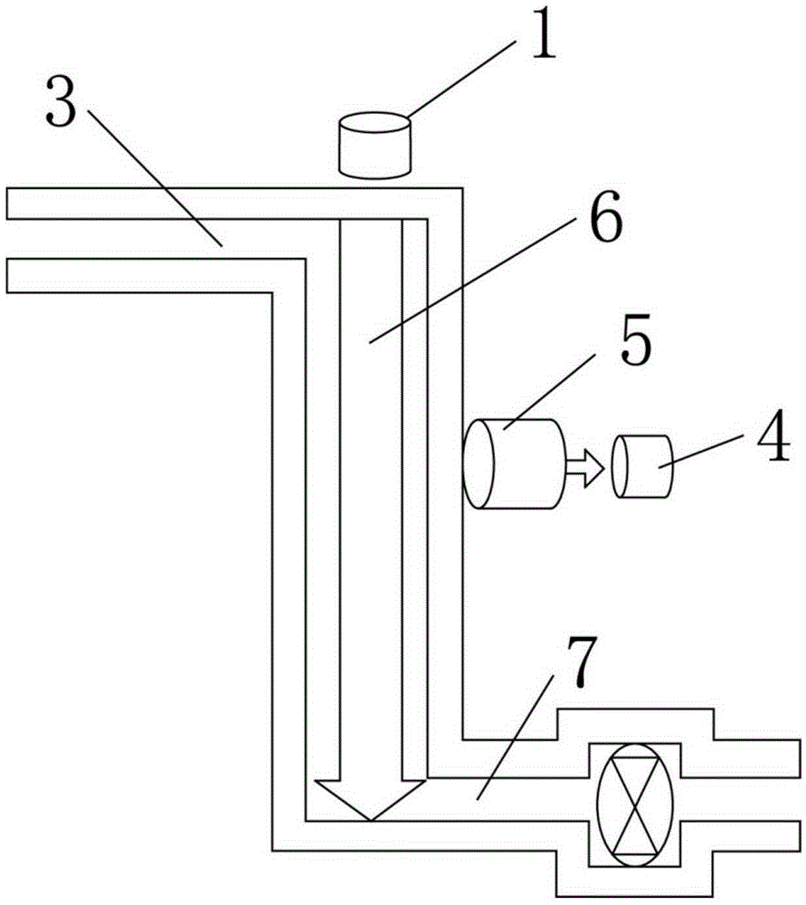
The prior art discloses a variety of air dust detectors, but the structure is complex, and the photoelectric receiver can not only receive the light scattered by the dust, but also receive the energy of the laser, resulting in the change of the dust concentration not only by the light intensity of the dust scattering but also by the received light. to the size of the laser energy
Inconvenient to promote the application

Method used


Image

  • An air dust detector
  • An air dust detector

Examples


Embodiment 1

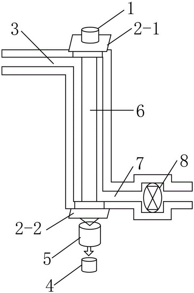
[0021] Such as figure 2 The described portable air dust detector based on light scattering includes a detection airflow passage 6, an air inlet 3 and an exhaust outlet 7 arranged on both sides of the detection airflow passage 6, and lasers arranged at both ends of the detection airflow passage 6 oppositely. The emitting device 1 and the light receiving device, the laser emitting end of the laser emitting device 1 and the scattered light output end of the light collecting device are respectively provided with mutually perpendicular polarizers 2-1- and 2-2.

[0022] In the present invention, the laser emitting end and the light receiving end are oppositely arranged at the first and last ends of the detection airflow channel, and the upper and lower polarizers (2-1 and 2-2) perpendicular to each other are respectively added to ensure the vertical incidence of the laser and the light received by the receiving end. Strong is almost entirely the scattered light intensity. At the s...

Embodiment 2

[0029] Compared with Embodiment 1, the only difference is that the detector described in this embodiment further includes a display device. After the specific light signal is processed and calculated, the specific dust concentration can be displayed by the display device. At the same time, the present invention can also customize early warning parameters in data processing and increase alarm device settings. When the dust concentration in the air exceeds a certain level, the display device can display the alarm in time, so that technicians can monitor the air quality more timely and effectively. and processing.

Embodiment 3

[0031] Compared with Embodiment 1, the only difference is that the detector described in this embodiment is driven by a charging device and has built-in software.


PUM


Abstract

The invention discloses an air dust detection instrument, which comprises a detection air flow passage, an air inlet opening, an exhaust opening, a laser emitter and a light collector, wherein the air inlet opening and an exhaust opening are formed at the two sides of the detection air flow passage, the laser emitter and the light collector are relatively arranged at the head end and the tail end of the detection air flow passage, and the laser emitting end of the laser emitter and the scattering light emergent end of the light collector are respectively provided with mutually vertical polaroids. The air dust detection instrument has the advantages that the carrying is convenient, the use is easy, the principle is simple, and the like. The length of the laser passing through the detection air flow is increased, and the dust detection sensitivity is improved. In addition, the data of the detection instrument is processed by PC (personnel computer) software, so the data processing is more accurate and stronger, the real-time test data can be obtained, the continuous dust concentration change curve can be obtained, the dust concentration early warning parameters can also be conveniently set, the real-time monitoring and the early warning processing can be carried out on the air dust concentration, and the air dust detection instrument belongs to a simple and portable air dust detection instrument with great popularization values.

Description

technical field [0001] The invention relates to a measuring instrument, in particular to a portable air dust detector based on light scattering. Background technique [0002] In the workplace and living environment, the dust suspended in the air is very harmful to the human body. Therefore, relevant departments advocate that the dust in the workplace must be tested. The prior art discloses a variety of air dust detectors, but the structure is complex, and the photoelectric receiver can not only receive the light scattered by the dust, but also receive the energy of the laser, resulting in the change of the dust concentration not only by the light intensity of the dust scattering but also by the received light. to the size of the laser energy. It is inconvenient to promote the application. [0003] Therefore, there is still a need to propose a portable dust detector with simple structure, convenient use and low cost. Contents of the invention [0004] The object of the p...

Claims


Application Information

Patent Timeline
Patent Type & Authority Patents(China)
IPC IPC(8): G01N15/06
Inventor 陈平邓玉新钮曼萍沈祥杨超
Owner HEFEI BOE OPTOELECTRONICS TECH
Learn More