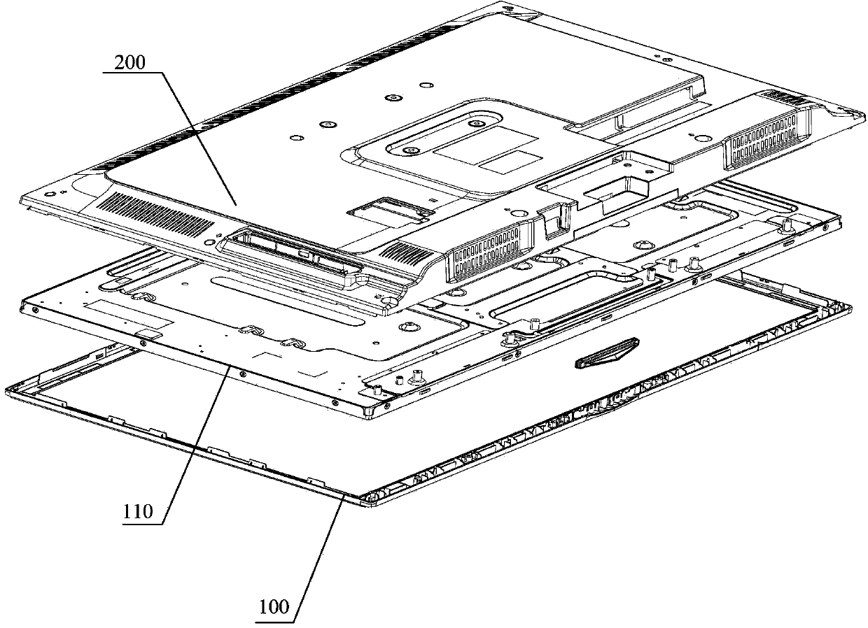
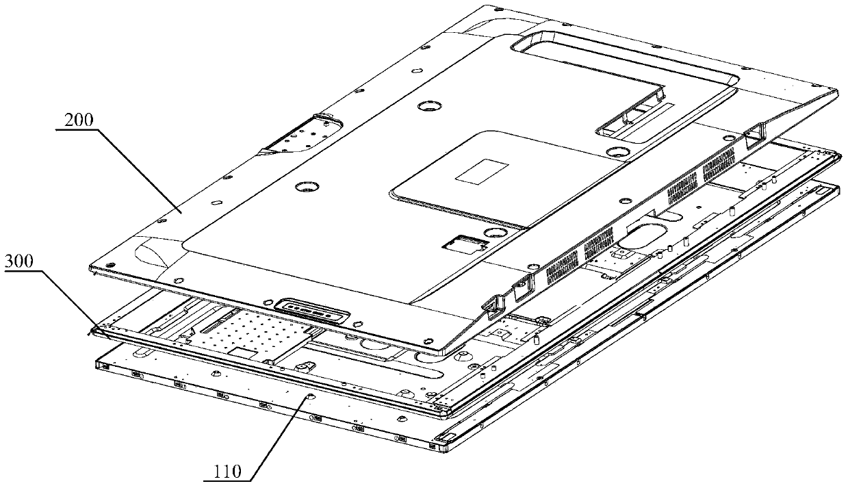
Liquid-crystal television
A technology of LCD TV and backplane, which is applied in the direction of TV, color TV, parts of color TV, etc. It can solve the problems such as the inability to install lighting components, and achieve a reliable display effect
- Summary
- Abstract
- Description
- Claims
- Application Information
AI Technical Summary
Problems solved by technology
Method used
Image
Examples
Embodiment 1
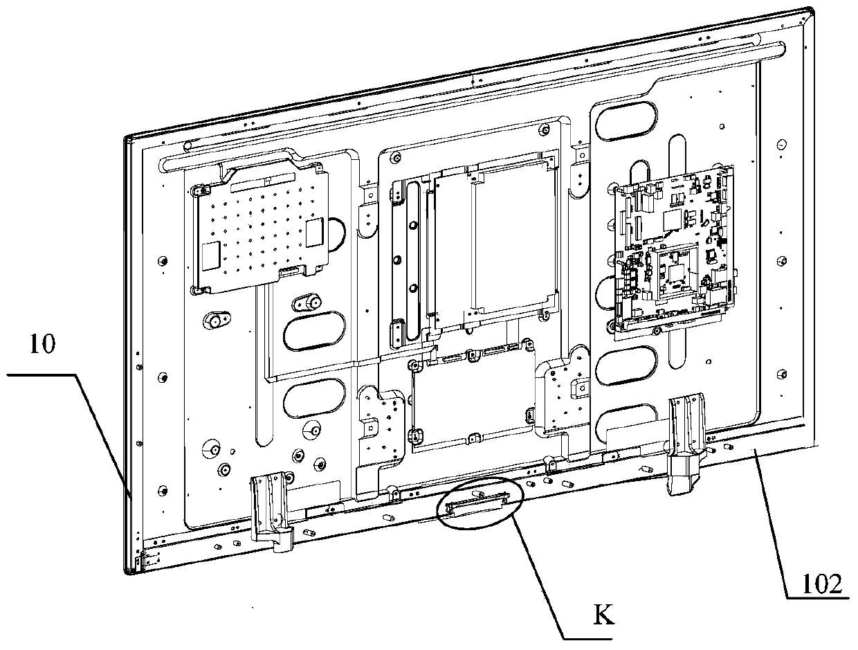
[0026] figure 2 It is a schematic structural diagram of an embodiment of a liquid crystal television of the present invention; image 3 for figure 2 Enlarged image at middle K; Figure 4 for figure 2 For the structural diagram of the lighting components in , please refer to Figure 2-4 , this embodiment provides a liquid crystal television, including a display screen 110, a casing and a lighting assembly 3, the casing includes a middle frame 10 and a rear casing (not shown in the figure), the middle frame 10 includes a side panel and is integrally connected with the side panel , and the bottom plate 102 with a through hole in the middle, the side plate is wrapped around the periphery of the display screen 110, the bottom plate 102 is wrapped around the back edge of the display screen 110, the bottom plate 102 is fixedly connected with the back plate of the display screen 110, and the rear shell covers the through hole of the bottom plate 102. hole, and is fixedly connec...
Embodiment 2
[0037] Figure 7 It is a schematic structural diagram of a lighting assembly in another embodiment of the present invention; this embodiment further improves the installation structure of the light emitting element and the light guide on the basis of the first embodiment.
[0038] Please refer to Figure 7 , in the liquid crystal television provided in this embodiment, a groove 30 may be provided at the top of the first section 301 of the light guide body 3 , and the light-emitting element 2 is arranged in the groove 30 . Among them, the shape and size of the groove 30 and the light-emitting element 2 can be reasonably set so that the light-emitting element 2 can be just engaged and fixed in the groove 30; for example, when the light-emitting element 2 is a rectangular plate, the groove 30 is the Part 2 has the same rectangular shape. When the luminous part 2 is circular or spherical, the groove 30 is also circular or spherical, so that the luminous part 2 cannot move in the ...
Embodiment 3
[0040] Figure 8 It is a perspective view of the lighting assembly in another embodiment of the LCD TV of the present invention; Figure 9 for Figure 8 Schematic diagram of the breakdown structure; Figure 10 for Figure 8 or Figure 9 Schematic diagram of the structure of the elastic clip firmware; Figure 11 for Figure 10 side view of Figure 12 for Figure 11 Schematic diagram of the cross-sectional structure of the middle position of ; further, such as Figure 8-12 As shown, in order to further improve the connection reliability between the light-emitting member and the light guide, an elastic clip 4 is also straddled on the groove 30 of the light guide 3, and the elastic clip 4 includes two oppositely arranged baffles 41 and a top plate 42 formed between the two baffles 41, the elastic fastener 4 is fixed on the light guide 3 through the engagement of the baffle 41 and the light guide 3, and straddles the top plate 12 of the opening of the groove 30 Stop the li...
PUM
 Abstract
Description
Claims
Application Information
 - R&D
- Intellectual Property
- Life Sciences
- Materials
- Tech Scout
- Unparalleled Data Quality
- Higher Quality Content
- 60% Fewer Hallucinations
Browse by: Latest US Patents, China's latest patents, Technical Efficacy Thesaurus, Application Domain, Technology Topic, Popular Technical Reports.
© 2025 PatSnap. All rights reserved.Legal|Privacy policy|Modern Slavery Act Transparency Statement|Sitemap|About US| Contact US: help@patsnap.com


