Unbalanced current detection device for IGBT circuit, driver and method for controlling IGBT circuit

A current detection device, detection device technology, applied in the direction of measuring device, measuring current/voltage, output power conversion device, etc., can solve the problems of long reaction time, oversized, expensive, etc., and achieve simplified calculation and judgment, short Effects of reaction time, simplification of calculation, and judgment of potential direction

Active Publication Date: 2016-06-22
VALEO EAUTOMOTIVE GERMANY GMBH
View PDF5 Cites 0 Cited by
  • Summary
  • Abstract
  • Description
  • Claims
  • Application Information

AI Technical Summary

Problems solved by technology

The bandwidth of the Hall effect sensor is low, the response time is long, it is difficult to apply to the IGBT module to measure the extremely short switching time of the IGBT
And the shunt resistor, if used for high current output, may end up being oversized and expensive

Method used


Image

  • Unbalanced current detection device for IGBT circuit, driver and method for controlling IGBT circuit
  • Unbalanced current detection device for IGBT circuit, driver and method for controlling IGBT circuit
  • Unbalanced current detection device for IGBT circuit, driver and method for controlling IGBT circuit

Examples


Embodiment Construction

[0036] In order to have a clearer understanding of the technical features, purposes and effects of the present invention, the specific implementation manners of the present invention will now be described with reference to the accompanying drawings.

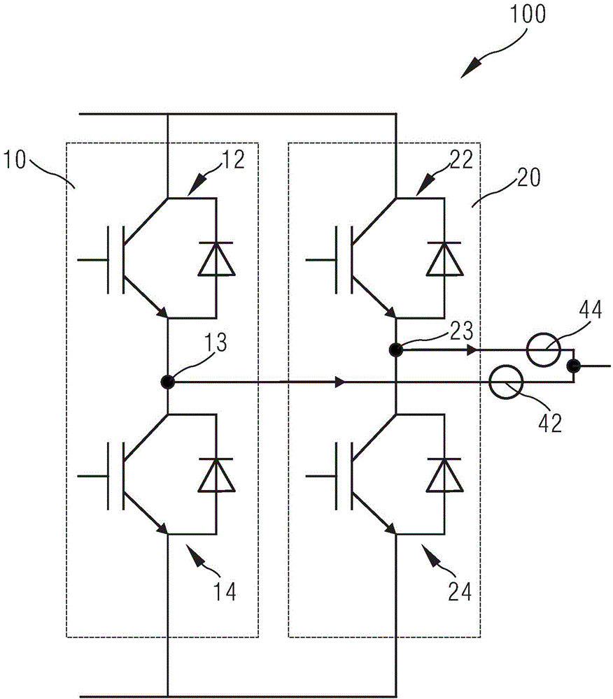
[0037] figure 1 An IGBT circuit 100 is shown, which may be, for example, an IGBT circuit in a driver for driving a large load with a large current, such as a motor of an electric vehicle or a UPS or an inductor. Such as figure 1 As shown, in order to obtain a larger output current, usually multiple IGBT modules are connected in parallel according to the actual driven load. figure 1 Only an IGBT circuit 100 with two parallel-connected IGBT modules 10 ; 20 is shown as an example, wherein each IGBT module 10 ; 20 in turn includes two series-connected IGBTs. The node 13 ; 23 between the two IGBTs 12 , 14 ; 22 ; 24 (that is, the connection point between the emitter and the collector of the two IGBTs) is the output terminal 13 ; 23 o...


PUM


Abstract

The present invention provides an unbalanced current detection device (40) for an IGBT circuit (100), a driver and a method for controlling the IGBT circuit (100). The IGBT circuit (100) comprises at least two IGBT modules (10; 20) in parallel connection. The current detection device (40) comprises two busbars (42; 44) in parallel connection, and the two busbars are parallelly arranged in a first plane (I) with an interval and can be connected to the output ends (13; 23) of any two IGBT modules (10; 20). The device also comprises a coil winding (45) and an unbalanced comparison module (50), wherein two end points of the coil winding (45) are connected to the input end of the unbalanced comparison module (50), and the unbalanced comparison module (50) judges the sequence of any two IGBT modules and a time difference.

Description

technical field [0001] The invention relates to an unbalanced current detection device for an IGBT circuit, a driver and a method for controlling the current output of the IGBT circuit, and particularly relates to the field of electric vehicles. IGBT usually refers to InsulatedGateBipolarTransistor in this field, that is, an insulated gate bipolar transistor. A circuit with an IGBT for driving a load is called an IGBT circuit. Background technique [0002] In order to drive large loads, such as motors, UPS, etc., an IGBT circuit with multiple IGBT modules connected in parallel is usually used. In order to obtain better performance, the driving circuit of each IGBT should enable each parallel-connected IGBT module to work at the same time, especially to enable the switching of the IGBT to occur simultaneously. If the IGBT switches are not at the same time, or the IGBT modules cannot work precisely at the same time, there will be a time difference in the output current of ea...

Claims


Application Information

Patent Timeline
Patent Type & Authority Applications(China)
IPC IPC(8): H03K17/567G01R19/10H02M1/00
CPCG01R19/10G01R15/181H03K2217/0027
Inventor 田山沈唐斌庄朝晖候贻真
Owner VALEO EAUTOMOTIVE GERMANY GMBH
Why Eureka
Try Eureka