Al technical title is built by PatSnap Al team. It summarizes the technical point description of the patent document.
A mosaic and lamp bead technology, which is applied in the direction of electrical components, circuits, semiconductor devices, etc., can solve the problems of short start-up time, large heat generation, small light output angle, etc.
Inactive Publication Date: 2013-02-13
DUJIANGYAN HUAGANG ELECTRONICS TECH
View PDF0 Cites 0 Cited by
Summary
Abstract
Description
Claims
Application Information
AI Technical Summary
This helps you quickly interpret patents by identifying the three key elements:
Problems solved by technology
Method used
Benefits of technology
Problems solved by technology
[0004] LED light source has many advantages such as long service life, short start-up time, remarkable energy-saving effect, no ultraviolet radiation, no mercury pollution, and high safety in use. It is gradually becoming the mainstream of lighting source. However, due to the unique luminous characteristics of LED, Many new requirements have been put forward for LED lighting applications, such as single light color, small light output angle, large heat generation, one-way conduction, etc., all of which need to be adapted in specific lighting solutions, involving from chip structure to chip packaging , from light source design to all levels of lamp structure, the packaging structure of existing LED lamp beads includes diode chips, lenses, gold wires, pins, packaging glue, heat sinks, bases and other components, and each component is assembled on the base through the base At the same time, most of the pins are in the shape of long strips, extending from the inner cavity of the base to the outside of the base, which can facilitate the welding between the lamp beads and the aluminum substrate. , a single pin form can no longer meet the application needs
Method used
Image
Click on the blue label to locate the original text in one second.
Reading with bidirectional positioning of images and text.
Examples
Embodiment Construction
[0014] The present invention will be further elaborated below in conjunction with the accompanying drawings.
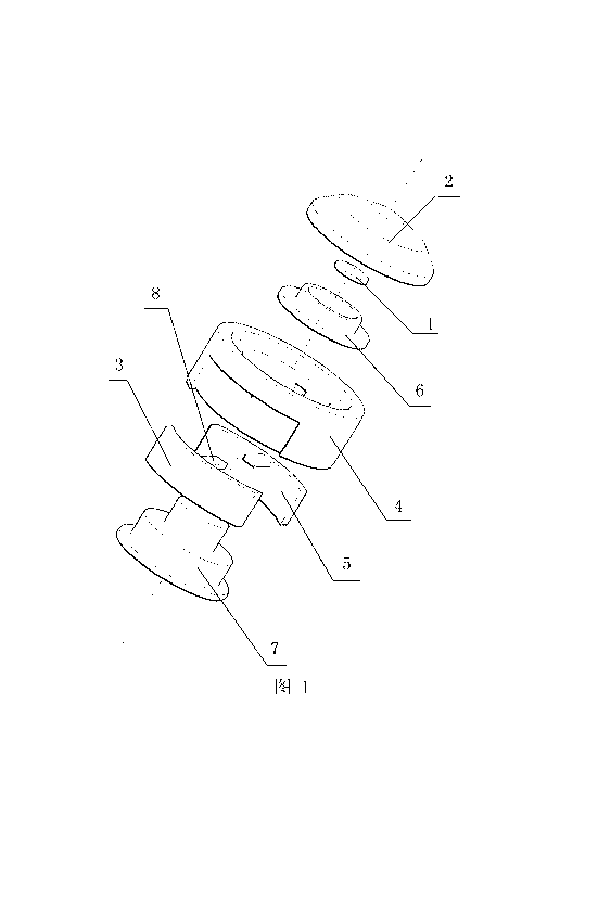
[0015] Such as figure 1 As shown, the LED lamp bead is in the shape of a round cake, and there are no long strip pins extending outside the lamp bead body. The base 4 and the pin 5 are composed of a curved outer leg 3 and a strip lead 8. The inner side of the base 4 is formed with a snap-in structure suitable for the shape of the heat sink 7, and the outer side of the base 4 is formed with two straps. The groove of the through hole, the heat sink 7 is embedded and fixed from the bottom of the base 4, the diode chip 1 is placed on the top surface of the heat sink 7, the two pins 5 are symmetrically placed on both sides of the base 4, and the outer pin 3 is completely stored in the In the groove of the base 4, a smooth lamp bead side wall is formed, and the lead piece 8 of the outer pin 3 is inserted into the inner cavity of the base through the through hole on the bas...
PUM
Abstract
The invention discloses an embedded type lamp bead which comprises a diode wafer (1), a lens (2), a gold wire, a pin (5), packaging glue, a heat sink (7) and a base (4), wherein the heat sink (7), the pin (5) and the lens (2) are assembled together through the base (4), the diode wafer (1) is arranged on the heat sink (7), the gold wire is connected with the diode wafer (1) and the pin (5), and the packaging glue is filled between the diode wafer (1) and the lens (2). The embedded type lamp bead is characterized in that the pin (5) comprises an outer pin (3) and a lead sheet (8), the ring side of the base (4) is provided with a groove and a through hole which are adapted to the outer pin (5) of the pin, and the pin (5) is penetrated in the ring side of the base (4) and is used for wrapping the base and extends to an inner cavity of the base (4) through the lead sheet (8). The embedded type lamp bead adopting the structure has a novel structure, and can adapt to installation demands of a pore plate type base.
Description
[0001] technical field [0002] The invention relates to the field of power light emitting diodes, in particular to a mosaic lamp bead. [0003] Background technique [0004] LED light source has many advantages such as long service life, short start-up time, remarkable energy-saving effect, no ultraviolet radiation, no mercury pollution, and high safety in use. It is gradually becoming the mainstream of lighting source. However, due to the unique luminous characteristics of LED, Many new requirements have been put forward for LED lighting applications, such as single light color, small light output angle, large heat generation, one-way conduction, etc., all of which need to be adapted in specific lighting solutions, involving from chip structure to chip packaging , from light source design to all levels of lamp structure, the packaging structure of existing LED lamp beads includes diode chips, lenses, gold wires, pins, packaging glue, heat sinks, bases and other components...
Claims
Application Information
Patent Timeline
Application Date:The date an application was filed.
Publication Date:The date a patent or application was officially published.
First Publication Date:The earliest publication date of a patent with the same application number.
Issue Date:Publication date of the patent grant document.
PCT Entry Date:The Entry date of PCT National Phase.
Estimated Expiry Date:The statutory expiry date of a patent right according to the Patent Law, and it is the longest term of protection that the patent right can achieve without the termination of the patent right due to other reasons(Term extension factor has been taken into account ).
Invalid Date:Actual expiry date is based on effective date or publication date of legal transaction data of invalid patent.