
A receiver with an improved driving structure

A technology of driving structure and receiver, applied in the field of receiver, can solve the problems of E-shaped armature limited structure, large receiver width, affecting stability, etc., and achieve the effect of expanding the application range, reducing the overall volume and improving the stability

Inactive Publication Date: 2014-04-23
SUZHOU HEARONIC ELECTRONICS
View PDF7 Cites 0 Cited by
  • Summary
  • Abstract
  • Description
  • Claims
  • Application Information

AI Technical Summary

Problems solved by technology

[0004] 1) The width of the overall receiver is too large, which directly causes its size to be difficult to reduce, which hinders the application of some specific fields, such as medical and other fields that require the volume of the receiver to be as small as possible;
[0005] 2) During the use of the receiver, the vibrating part needs to swing up and down continuously to achieve the driving effect, so the firm support for the vibrating part is particularly important, but the current E-shaped armature, its support for the vibrating part Basically, they are all concentrated on one connection point, which directly affects the firm support for the vibrating part and affects its stability. Poor stability may also cause problems such as power consumption;
[0006] 3) The original E-shaped armature is limited by its structure, and it is generally connected to the shell and other components by spot welding, which also directly affects the reliability of the connection, and this spot welding method also has operational advantages. Disadvantages that the process is difficult and difficult to grasp

Method used


Image

  • A receiver with an improved driving structure
  • A receiver with an improved driving structure
  • A receiver with an improved driving structure

Examples


Embodiment Construction

[0025] Preferred embodiments of the present invention will be described in detail below in conjunction with the accompanying drawings.

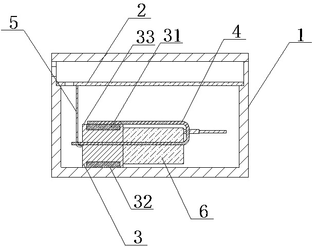
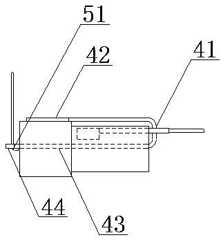
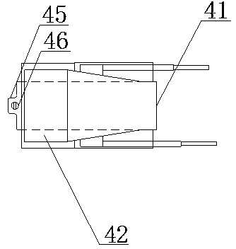
[0026] Such as Figure 1-5 As shown, in the first embodiment of the receiver with the improved driving structure involved in the present invention, it includes the casing 1 and the diaphragm 2, and also includes: the iron core 3, the lower end surface 32 of which is welded or bonded The entire surface is fixedly connected to the inner wall of the housing 1, and the through hole of the iron core 3 is covered with a magnet 31; the side of the armature 4 is U-shaped, starting from the bending part 41, and one end of the armature 4 faces The front extends to the upper end surface 33 of the iron core 3 and forms a first connection surface 42 there. The first connection surface 42 and the upper end surface 33 are fixedly connected to the entire surface by welding or bonding. The other end of the armature 4 As the vibrating part 43 extends forward ...


PUM


Abstract

The invention discloses a receiver with an improved driving structure. The receiver comprises a housing, a vibrating diaphragm, an iron core, an armature, a guide probe, and a coil. The bottom end face of the iron core is fixedly connected with the inner wall of the housing. A magnet is pasted on a through hole of the iron core. The side surface of the armature is in a U shape. By using a bending portion in the middle of the armature as an origin, one end of the armature is extended forwardly to the top end face of the iron core and forms a first connecting face at the top end face of the iron core. The first connecting face is fixedly connected with the top end face. Used as a vibrating portion, the other end of the armature is extended forwardly and passes through the through hole of the iron core. A part, exposed out of the iron core, of the other end of the armature forms a second connecting face. One end of the guide probe is connected with the vibrating diaphragm, while the other end of the guide probe is connected with the second connecting surface. The coil is disposed between the bending portion and the iron core and is sleeved on the vibrating portion. The receiver has decreased integral volume and enhanced integral stability.

Description

technical field [0001] The invention relates to a receiver, in particular to a receiver with an improved driving structure. Background technique [0002] The receiver is an electro-acoustic device that converts audio electrical signals into sound signals without sound leakage. It is widely used in communication terminal products to realize audio playback, mainly in mobile phones, earphones and hearing aids. Among them, the driver part of the receiver is the core device of the whole receiver, and the quality of the driver part determines the quality of the whole receiver. [0003] The current drive part mainly includes several major components such as armature, coil and iron core. In order to facilitate the installation of the coil and iron core, and to facilitate the installation of the entire drive part into the casing, the current armature is generally designed as an E shape. , The periphery of the E-shaped armature is used to install in the shell, and the rod body in the...

Claims


Application Information

Patent Timeline
Patent Type & Authority Applications(China)
IPC IPC(8): H04R1/10
Inventor 周巍
Owner SUZHOU HEARONIC ELECTRONICS
Learn More