
Clamping device for plate-shaped workpiece

A technology of clamping device and plate-shaped workpiece, which is applied in the direction of clamping device, positioning device, metal processing machine parts, etc., can solve the problems of easy crushing of the workpiece, large force on the workpiece, and asynchronous clamping between the two pressure plates.

Inactive Publication Date: 2014-04-30
CHONGQING TIANZHIDAO SCI & TECH DEV
View PDF0 Cites 12 Cited by
  • Summary
  • Abstract
  • Description
  • Claims
  • Application Information

AI Technical Summary

Problems solved by technology

[0003] However, the existing clamping device with two pressure plates has the phenomenon that the clamping of the two pressure plates is not synchronized. In addition, the two pressure plates generally clamp the workpiece from both sides of the plate-shaped workpiece. When the pressure plate clamps the workpiece, the contact between the pressure plate and the workpiece The surface is small, resulting in a large local force on the workpiece, and the workpiece is easily crushed

Method used


Image

  • Clamping device for plate-shaped workpiece

Examples


Embodiment Construction

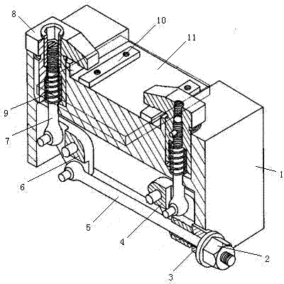
[0011] like figure 1 As shown, the clamping device for a plate-shaped workpiece includes two pressing plates, a transmission mechanism and a base 1 with a clamping table 11, and two elastic pads 10 are arranged on the holding table 11, wherein the two pressing plates It is the hook head pressure plate 8 that is arranged oppositely on both sides of the clamping table 11. The transmission mechanism includes a screw rod 5, a left turning block 6, a right turning block 4 and two transmission rods 7, and the transmission rod 7 is sleeved with a reset Spring 9, the upper end of return spring 9 is fixedly connected to the transmission rod 7, the lower end is supported on the base 1, the upper end of the transmission rod 7 is threaded with the hook head pressure plate 8, and the middle part of the left turning block 6 is hinged on a hook head pressure plate 8 below On the base 1, the upper part is hinged with the bottom end of a transmission rod 7, and the lower part is hinged with on...


PUM


Abstract

The invention relates to a clamping device, in particular to a clamping device for a plate-shaped workpiece. The clamping device comprises two pressing plates, a transmission mechanism and substrates provided with a clamping table, wherein the two pressing plates are hook-headed pressing plates oppositely arranged on the two sides of the clamping table; the transmission mechanism comprises a screw, a left rotating block, a right rotating block and two transmission rods; a reset spring is sleeved on each transmission rod; the upper ends of each transmission rods are connected with the hook-headed pressing plates; the middle part of the left rotating block is hinged to the substrate below a hook-headed pressing plate, the upper part of the left rotating block is hinged to the bottom of one transmission rod, and the lower part of the left rotating block is hinged to one end of the screw; the upper part of the right rotating block is hinged to the substrate below the other hook-headed pressing plate, and the middle part of the right rotating block is hinged to the bottom of the other transmission rod; the screw penetrates through the lower part of the right rotating block, the far hinged end of the screw is provided with an adjusting nut, and a sliding sleeve is arranged between the adjusting nut and the right rotating block. The two pressing plates are used for clamping the workpiece simultaneously, and the contact surface between each pressing plate and the workpiece is large, and the workpiece is not easy to be broken by clamping.

Description

technical field [0001] The invention relates to a clamping device, in particular to a clamping device for a plate-shaped workpiece. Background technique [0002] In mechanical processing, it is usually necessary to use a clamping device to clamp the workpiece first, and then process on the workpiece, so the clamping device is widely used. In the clamping device, if there are two pressure plates, it is necessary to ensure that the two pressure plates Simultaneously compress the workpiece. [0003] However, the existing clamping device with two pressure plates has the phenomenon that the clamping of the two pressure plates is not synchronized. In addition, the two pressure plates generally clamp the workpiece from both sides of the plate-shaped workpiece. When the pressure plate clamps the workpiece, the contact between the pressure plate and the workpiece The surface is small, resulting in a large local force on the workpiece, and the workpiece is easily crushed. Contents ...

Claims


Application Information

Patent Timeline
IPC IPC(8): B23Q3/06
CPCB23Q3/069B23Q2703/02
Inventor 姜静慧
Owner CHONGQING TIANZHIDAO SCI & TECH DEV
Learn More