
Device for separating permanent magnets of motors

A technology of permanent magnets and separation rods, which is applied in the direction of hand-held tools and manufacturing tools, and can solve the problems of permanent magnet motor rotor manufacturing troubles, damage, permanent magnet damage, etc.

Inactive Publication Date: 2015-07-22
SHANDONG HUALI ELECTRIC MOTOR GRP
View PDF11 Cites 0 Cited by
  • Summary
  • Abstract
  • Description
  • Claims
  • Application Information

AI Technical Summary

Problems solved by technology

[0002] The rotor of a rare earth permanent magnet motor is generally composed of a permanent magnet and an iron core. The permanent magnet is placed on the surface of the rotor iron core or in the rotor iron core according to certain rules. Together or the permanent magnet and the magnetizer are attracted together, which will cause a lot of trouble to the manufacture of the permanent magnet motor rotor.
It is very difficult to separate the permanent magnets or permanent magnets that are attracted together from the magnetic conductor, and it is easy to cause damage to the permanent magnets and even cause personal injury

Method used


Image

  • Device for separating permanent magnets of motors
  • Device for separating permanent magnets of motors
  • Device for separating permanent magnets of motors

Examples


Embodiment Construction

[0011] The present invention will be further described below in conjunction with the accompanying drawings and embodiments.

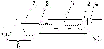
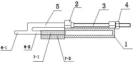
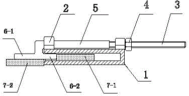
[0012] as attached figure 1 Shown, a kind of device that is used for separating the permanent magnet of electric motor, this device comprises a separation box 1, and this separation box is a elongated box body, and the left end of box body is open, and right end is closed, and at the top of open end and closed end The outside of the box body is respectively provided with a guide sleeve 2, between the two guide sleeves is provided with a traction screw 3, one end of the traction screw 3 passes through the guide sleeve at the top of the closed end and is provided with a traction nut 4 on the protruding screw body.

[0013] as attached figure 1 As shown, one end of the separation rod 5 passes through the guide sleeve on the top of the open end of the box body and is fixed to the end of the traction screw 3. The end of the separation rod 5 outside the guid...


PUM


Abstract

The invention belongs to the technical field of manufacture for motors, and provides a device for separating permanent magnets of motors. The device aims to solve technical problems caused when permanent magnets in suction states are separated in current motor manufacturing procedures. The device comprises a separating box. One end of a box body of the separating box is open, the other end of the box body is closed, guide sleeves are arranged on the outer side of the box body and are respectively positioned on the top of the open end and the top of the closed end of the box body, a traction screw is arranged between the two guide sleeves, one end of the traction screw penetrates the guide sleeve on the top of the closed end of the box body, and a traction nut is arranged on an extending screw body of the traction screw; one end of a separating rod penetrates the guide sleeve on the top of the open end of the box body and is fixed to an end of the traction screw, the end, which is positioned on the outside of the guide sleeve on the top of the open end of the box body, of the separating rod is downwardly and perpendicularly bent, a horizontal rod is fixed to the bent end of the separating rod, the horizontal rod and the separating rod are parallel to each other and face the open end of the box body, and the horizontal rod is divided into a left rod and a right rod by the bent end of the separating rod. The device for separating the permanent magnets has the advantage that the permanent magnets which are sucked to one another can be safely and stably separated from one another by the aid of the device.

Description

technical field [0001] The invention belongs to the technical field of motor manufacturing, and in particular relates to a device for separating permanent magnets of a motor. Background technique [0002] The rotor of a rare earth permanent magnet motor is generally composed of a permanent magnet and an iron core. The permanent magnet is placed on the surface of the rotor iron core or in the rotor iron core according to certain rules. Together or the permanent magnet and the magnetizer are attracted together, which will cause a lot of trouble in the manufacture of the permanent magnet motor rotor. It is very difficult to separate the attracted permanent magnet or the permanent magnet from the magnetic conductor, and it is easy to cause damage to the permanent magnet and even cause personal injury. Contents of the invention [0003] In order to solve the technical problems existing in the separation of the permanent magnets in the adsorption state in the current mo...

Claims


Application Information

Patent Timeline
Patent Type & Authority Patents(China)
IPC IPC(8): B25B27/14
CPCB25B27/14
Inventor 李海成王庆东马志强
Owner SHANDONG HUALI ELECTRIC MOTOR GRP
Learn More