
Vertical MEMS (Micro Electro Mechanical System) bent probe inserting device and method

A pin insertion device and vertical technology, applied in the field of semiconductor chip testing, can solve the problems of pin position offset, spillage, bending, etc., and achieve the effect of low cost and high precision

Active Publication Date: 2022-05-13
MAXONE SEMICON CO LTD
View PDF8 Cites 0 Cited by
  • Summary
  • Abstract
  • Description
  • Claims
  • Application Information

AI Technical Summary

Problems solved by technology

[0015] (4) Provide a vertical MEMS curved probe pin insertion method, which solves the current problems of needle position offset, spillage, and bending caused by manual pin insertion and needle replacement

Method used


Image

  • Vertical MEMS (Micro Electro Mechanical System) bent probe inserting device and method
  • Vertical MEMS (Micro Electro Mechanical System) bent probe inserting device and method
  • Vertical MEMS (Micro Electro Mechanical System) bent probe inserting device and method

Examples


Embodiment 1

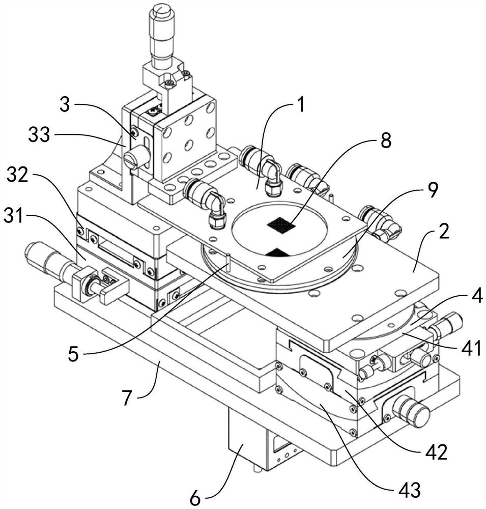
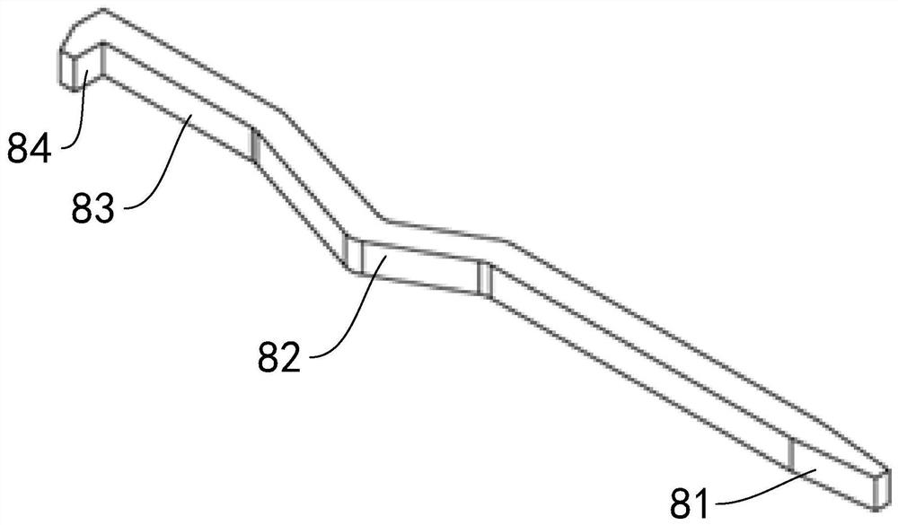
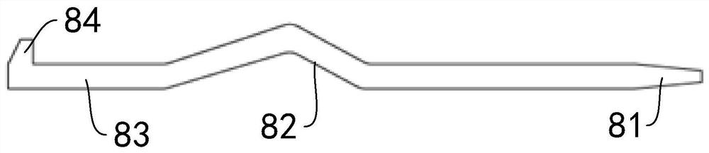
[0090] Reference attached figure 1 to the attached Figure 12As shown, the first embodiment of the present invention proposes a vertical MEMS curved probe pin insertion device for inserting the vertical MEMS curved probe into the probe card 9, the probe has a needle tip 81, a needle belly 82. Needle tail 83 and needle hook 84, the needle belly 82 of the probe is a curved structure, the central axis extension line of the needle tip 81 and the central axis extension line of the needle tail 83 are parallel, the probe card 9 includes an upper cover plate 91 and a lower cover plate 92, the upper cover plate 91 is provided with an upper probe hole 911 for the needle tail 83 to pass through, and the lower cover plate 92 is provided with a lower probe hole for the needle tip 81 to pass through. The probe hole 921 is characterized in that the cross section of the lower probe hole 921 is larger than that of the upper probe hole 911, and the pin insertion device includes: an upper fixi...

Embodiment 2

[0133] Embodiment 2, refer to the attached Figure 13 to the attached Figure 15 As shown, the second embodiment of the present invention proposes a method for inserting a Cobra probe. The method is implemented using the device described in the first embodiment, and the method includes the following steps:

[0134] Step 1: Pin Preparation

[0135] 1. The first mobile station 311 moves to a safe position;

[0136] 2. The second mobile station 321 moves to a safe position;

[0137] 3. The third mobile platform 331 ascends and moves to a safe position;

[0138] 4. The first tilt table 411 is moved to a safe position;

[0139] 5. The second tilt table 421 is moved to a safe position;

[0140] 6. The third tilt table 431 is moved to a safe position;

[0141] 7. The vacuuming air circuit of the upper fixing plate 11 is closed, and it is in a normal air pressure state;

[0142] 8. The vacuuming air circuit of the lower fixing plate 21 is closed, and it is in a normal air press...


PUM


Abstract

The invention discloses a vertical MEMS (Micro Electro Mechanical System) bent probe inserting device and a probe inserting method thereof. The needle inserting device comprises an upper fixing structure, a lower fixing structure, a translation structure, an inclination structure, a positioning guide structure and a visual detection structure, and is configured in a manner that when the needle inserting device is in a working position, when the inclination mechanism drives the lower fixing structure to incline, the needle tail of a probe has degrees of freedom of inclined rotation on a theta axis, an X axis and a Y axis in a space of a lower probe hole, and the needle tail of the probe has degrees of freedom of inclined rotation on the theta axis, the X axis and the Y axis; the upper probe holes in the upper cover plate are in one-to-one vertical correspondence with the lower probe holes in the lower cover plate, and the guide holes in the upper cover plate are in one-to-one vertical correspondence with the guide columns on the lower fixing structure. By means of a mechanical structure which is simple in structure and extremely high in reliability and precision, it can be guaranteed that the upper cover plate and the lower cover plate are stable and separated without deviation through pin insertion, the problems of pin bending, repeated alignment, low efficiency and the like are solved, cost is low, precision is high, and the pin insertion yield of the MEMS bent probe with the special structure is guaranteed.

Description

technical field [0001] The invention relates to the technical field of semiconductor chip testing, in particular to a vertical MEMS curved probe pin device and a pin insertion method for high-end probe card production. Background technique [0002] The probe card is an important tool for testing chip yield. With the continuous shortening of the chip manufacturing process, the chip pin spacing is becoming smaller and smaller, and the conventional probe card can no longer be tested. In order to meet the testing requirements, vertical MEMS probes manufactured by MEMS process are used for chip pin testing. [0003] For different types of chip testing requirements, some need to use curved vertical MEMS probes for testing. [0004] Reference is attached Figure 2A to the attached Figure 2C The schematic diagram of the structure of the vertical MEMS curved probe is shown. The vertical MEMS curved probe is characterized by a small size (section 60μm*60μm) with a curved arc struct...

Claims


Application Information

Patent Timeline
IPC IPC(8): G01R31/28G01R1/067
CPCG01R31/28G01R1/067
Inventor 于海超徐兴光周培清
Owner MAXONE SEMICON CO LTD
Features
  • Generate Ideas
  • Intellectual Property
  • Life Sciences
  • Materials
  • Tech Scout
  • Unparalleled Data Quality
  • Higher Quality Content
  • 60% Fewer Hallucinations
Learn More