Overload protecting structure of material pushing mechanism

A push mechanism and overload protection technology, applied in the field of overload protection structures, can solve problems such as increased production cost, deformation and damage, and reduced work efficiency.

Active Publication Date: 2014-04-30
GUANGZHOU TECH LONG PACKAGING MACHINERY CO LTD
View PDF7 Cites 0 Cited by
  • Summary
  • Abstract
  • Description
  • Claims
  • Application Information

AI Technical Summary

Problems solved by technology

[0002] The material pushing mechanism of the packaging equipment groups the filled bottles according to the preset number of each group, so that there is a distance between adjacent groups of bottles, which is convenient for subsequent packaging of each group of bottles. At present, the material pushing mechanism uses catch-up The bottle rod groups the bottles according to the number of requirements. By fixing the two ends of the bottle driving rod on the corresponding conveying chain, the conveying chain drives the bottle driving rod to move, so as to realize the function of grouping the bottle driving rod. However, due to the bottle driving The rod is a rigid part, and its connection with the conveyor chain is also rigid. Therefore, when the conveyor belt transfers the bottle to the material pushing mechanism, once a bottle is dumped, the bottle driving rod will press on the dumped bottle, and the dumped bottle will fall. The bottle body will also lift up the corresponding position of the bottle-driving rod, but the two ends of the bottle-driving rod will not be lifted up, so that the fallen bottle will be deformed and damaged under the pressure of the bottle-driving rod, and at the same time, the bottle-driving rod will be easily damaged. The reaction force of the dumped bottle is affected by deformation or fracture, which increases the production cost; in addition, when the bottle driving lever presses the dumped bottle, the operator does not notice the abnormality. Therefore, in order to take out the dumped bottle in time, the Under the joint action of the bottle driving rod and the conveyor belt, the dumped bottles will continue to move forward, resulting in the failure to pack later and reducing work efficiency

Method used


Image

  • Overload protecting structure of material pushing mechanism
  • Overload protecting structure of material pushing mechanism
  • Overload protecting structure of material pushing mechanism

Examples


Embodiment Construction

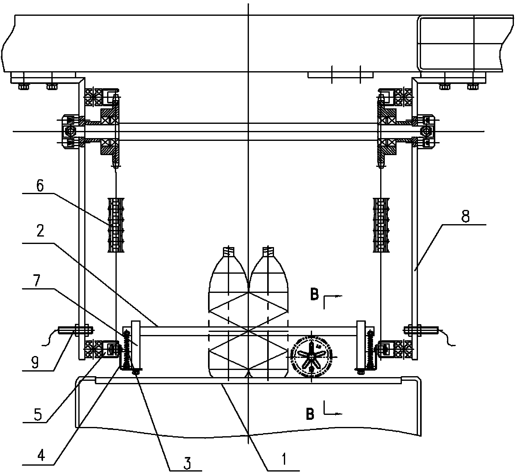
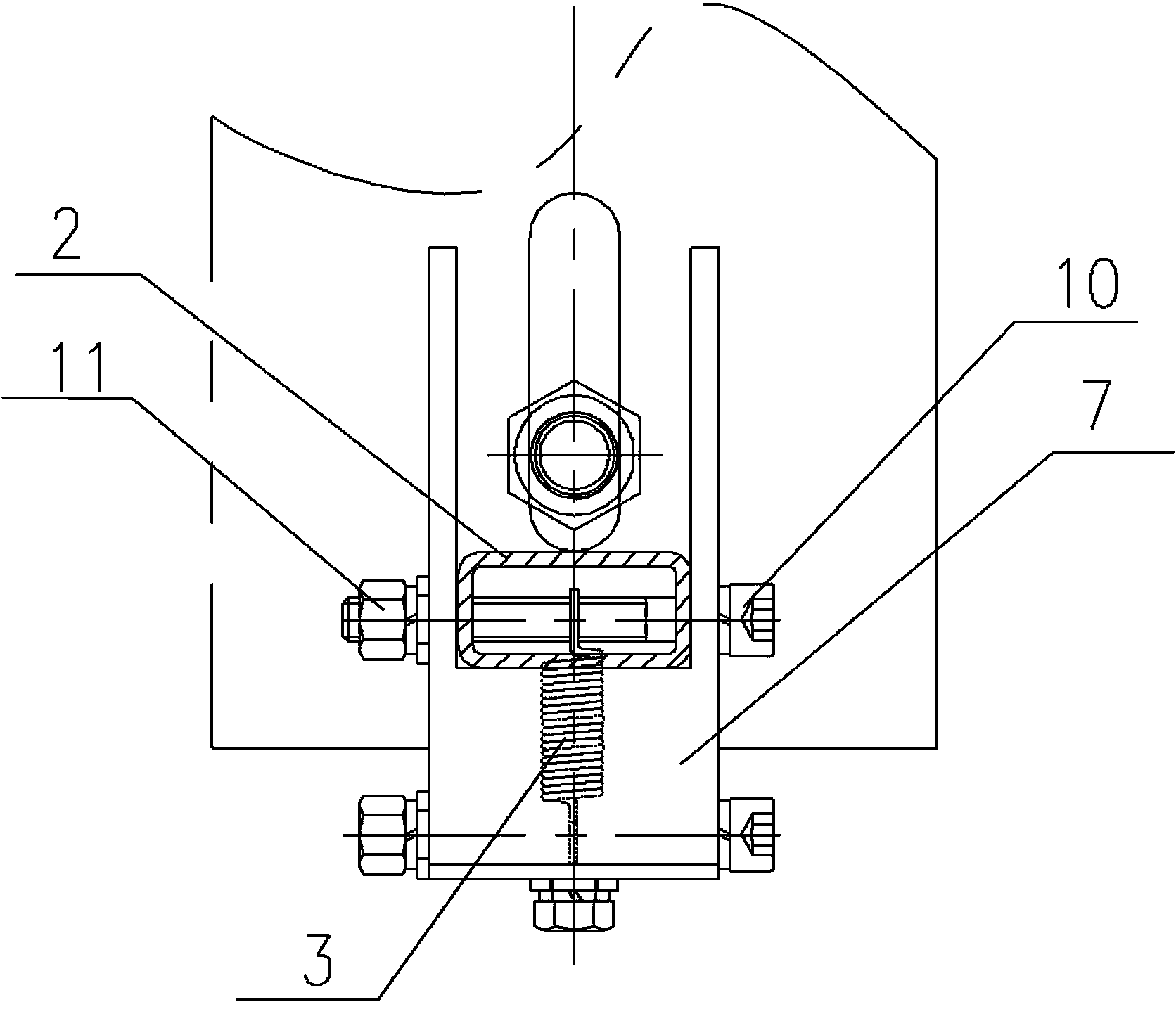
[0012] An overload protection structure of a material pushing mechanism, such as Figure 1 to Figure 4 As shown, it includes the bottle-driving bar 2 arranged on the top of the conveyor belt 1, the two ends of the bottle-driving bar 2 are fixedly connected with one end of the corresponding spring 3 respectively, and the other end of the spring 3 is fixed on the corresponding support seat 4, and the support seat 4 is connected with the corresponding spring 3. The conveyor chain 6 that is installed in the fixed guide groove 5 and can move relative to the fixed guide groove 5 is fixedly connected.

[0013] The two ends of the bottle driving bar 2 that can slide along the guide block 7 are respectively connected with the guide block 7 fixed on the support base 4 .

[0014] On both sides of the conveying chain 6, the protective plate 8 with the fixed guide groove 5 is installed with a photoelectric switch 9. When a bottle is dumped, the bottle driving rod 2 is pressed on the body o...


PUM


Abstract

An overload protecting structure of a material pushing mechanism comprises a bottle pushing bar arranged above a conveying belt. Two ends of the bottle pushing bar are respectively fixedly connected with one end of the corresponding spring, the other end of each spring is fixed to a corresponding support, and each support is fixedly connected with a conveying chain that is mounted in a fixed guide groove and capable of moving relative to the same. The bottle pushing bar and the supports are connected through the springs, in other words, the bottle pushing bar is connected movably, and thus the bottle pushing bar pressing the bottles can be lifted integrally; the force of the bottle pushing bar applied to the bottles is reduced along with extension of the springs under stressing to avoid damaging the bottles; if operators find abnormal operation, the operators can lift the bottle pushing bar to remove the tilting bottles, and meanwhile, the bottle pushing bar can reset under elasticity of the springs; due to elastic connection between the bottle pushing bar and the supports, the tilting bottles can be prevented from being damaged by the bottle pushing bar, deformation and breakage of the bottle pushing bar are avoided, and production cost is lowered greatly.

Description

technical field [0001] The invention relates to a material pushing mechanism of packaging equipment, in particular to an overload protection structure in the material pushing mechanism. Background technique [0002] The material pushing mechanism of the packaging equipment groups the filled bottles according to the preset number of each group, so that there is a distance between adjacent groups of bottles, which is convenient for subsequent packaging of each group of bottles. At present, the material pushing mechanism uses catch-up The bottle rod groups the bottles according to the number of requirements. By fixing the two ends of the bottle driving rod on the corresponding conveying chain, the conveying chain drives the bottle driving rod to move, so as to realize the function of grouping the bottle driving rod. However, due to the bottle driving The rod is a rigid part, and its connection with the conveyor chain is also rigid. Therefore, when the conveyor belt transfers t...

Claims


Application Information

Patent Timeline
Patent Type & Authority Applications(China)
IPC IPC(8): B65B61/28B65G21/20
Inventor 陈海强邱建国曾国友周晶
Owner GUANGZHOU TECH LONG PACKAGING MACHINERY CO LTD
Why Eureka
Try Eureka