Conductive corrugated tube

A corrugated tube and conductive tube technology, applied in conductors, hoses, circuits, etc., can solve the problems of easy deformation and breakage of copper tubes, high cost, low efficiency, etc., to improve power supply reliability, save non-ferrous metals, and widen social benefits. Effect

Inactive Publication Date: 2009-06-17
罗志昭
View PDF1 Cites 6 Cited by
  • Summary
  • Abstract
  • Description
  • Claims
  • Application Information

AI Technical Summary

Problems solved by technology

From the above, the waste of copper is particularly serious, the temperature rises, and the cost is high
[0004] In addition, hollow cables have also been proposed, but they cannot be implemented in practical applications. The reason is that they cannot be freely bent and laid out like wires and cables. Its structure is actually a small copper tube with a flat surface. The medium copper tube is easy to deform and break, and the current carrying capacity is small, because it is only a single-layer copper tube, and the current carrying capacity is limited
[0005] In addition, the existing conductor is a whole in the conduction process and has no ability to melt ice
In the event of an ice and snow disaster, a large area of ​​power grid transmission lines will be crushed by ice. The reason is that the heat generated by the existing conductors cannot withstand low-temperature freezing. To melt the ice and snow on the conductors, the high-voltage power supply must be stopped. Using a large-capacity current generator to conduct phase-to-phase short-circuit heating to melt ice is not ideal, and the current equipment capacity is not enough to realize it, and the ice-melting process requires large-scale power outages, high cost and low efficiency.

Method used


Image

  • Conductive corrugated tube
  • Conductive corrugated tube
  • Conductive corrugated tube

Examples


Embodiment Construction

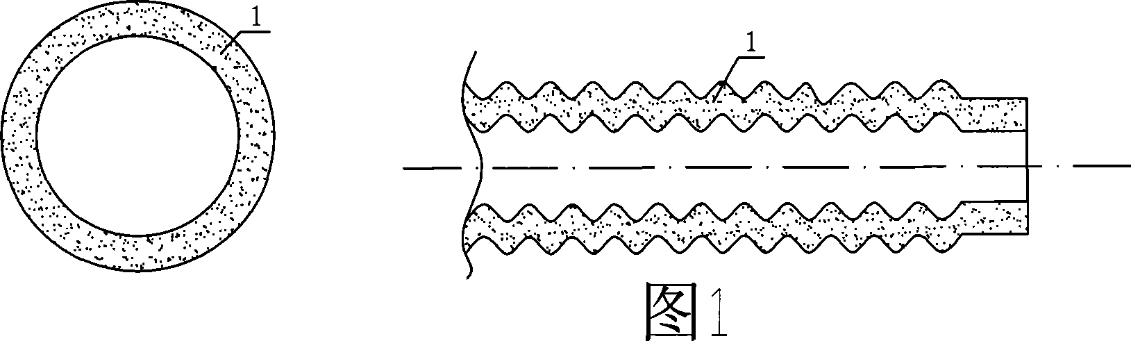
[0028] According to the requirements of the current carrying capacity, one layer of conductive bellows or multi-layer conductive bellows is selected as the wire and cable conductor, for example: the outer diameter of the conductive bellows is Φ50mm, the wall thickness is 2mm, and the cross-sectional area is 300mm 2 Rated current 900A, current density: 3(A / mm 2 ), temperature rise 50k.

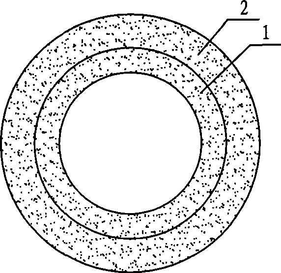
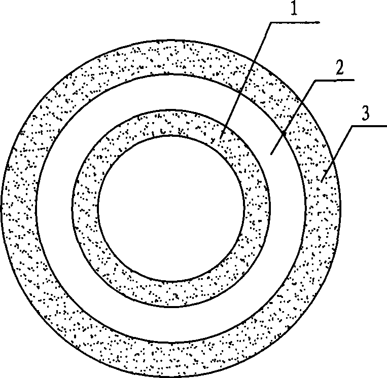
[0029] 1. The method of manufacturing conductive bellows: According to the current carrying capacity requirements, select the appropriate copper strip or aluminum strip (thickness 0.1mm ~ 15mm), use the welded pipe production line to produce the conductive tube first, and use the rolling machine to press the conductive tube into Conductive corrugated pipe (Figure 1); if multi-layer conductive corrugated pipe is required, firstly use the welded pipe production line to produce multi-layer conductive pipe, and use a rolling machine to press the multi-layer conductive pipe into a multi-layer conduc...


PUM

PropertyMeasurementUnit
thicknessaaaaaaaaaa

Abstract

The invention provides a conductive corrugated pipe of corrugated pipe structure, which has the advantages of wires and cables as flexibility, and can be freely bended and released as wires and cables, has the advantages of hollow conductors as high current carrier amount, and is a multilayer conductive corrugated pipe capable of improving the effective section area of transmission current. The corrugated pipe should be added with a cable core before being applied in overhead lines, the corrugated pipe is made from copper or aluminum, the adjacent corrugated pipes are provided with an insulation layer therebetween. Additionally, the ratio current will not change when the temperature is lower than 4DEG C, the conductors of the corrugated pipe reduces some section area, the current is transmitted by the corrugated pipe, the temperature increase of the whole corrugated pipe conductor will be higher than former temperature increase, to fuse ice and snow.

Description

technical field [0001] The invention relates to the use of power generation, power transmission and transformation, and power consumption units for conveying various voltage levels and large currents, which is safe and energy-saving, and belongs to a new invention technology. Background technique [0002] I have applied for a multi-split copper or aluminum busbar invention patent (patent number: 200710029646.2) in which the multi-split copper or aluminum busbar (pipe busbar) adopts multi-split conductors, and there is an insulating layer between the conductors, and each conductor has two conductors. noodle. This conductor is a rigid conductor, and the production and transportation length is less than 13 meters. There are many joints during installation, and the conductor cannot be bent freely. The insulating material is easily torn during the construction of the bending pipe, and the insulation is destroyed. Safety performance is not guaranteed. [0003] The existing wire ...

Claims


Application Information

Patent Timeline
Patent Type & Authority Applications(China)
IPC IPC(8): H01B5/06H01B7/16H01B7/17H01B7/42F16L11/15F16L11/127H05B3/58
Inventor 罗志昭
Owner 罗志昭
Why Eureka
Try Eureka