Orientation transmission mechanism for workpiece with end face with hole

A transmission mechanism and workpiece technology, applied in the direction of conveyors, conveyor objects, transportation and packaging, etc., can solve problems such as inability to realize workpieces

Inactive Publication Date: 2014-04-30
CHONGQING MING SHIELD ELECTROMAGNETIC VALVE
View PDF0 Cites 2 Cited by
  • Summary
  • Abstract
  • Description
  • Claims
  • Application Information

AI Technical Summary

Problems solved by technology

[0003] The technical problem to be solved by the present invention is that in the prior art, the directional transmission of wo

Method used


Image

  • Orientation transmission mechanism for workpiece with end face with hole

Examples


Embodiment Construction

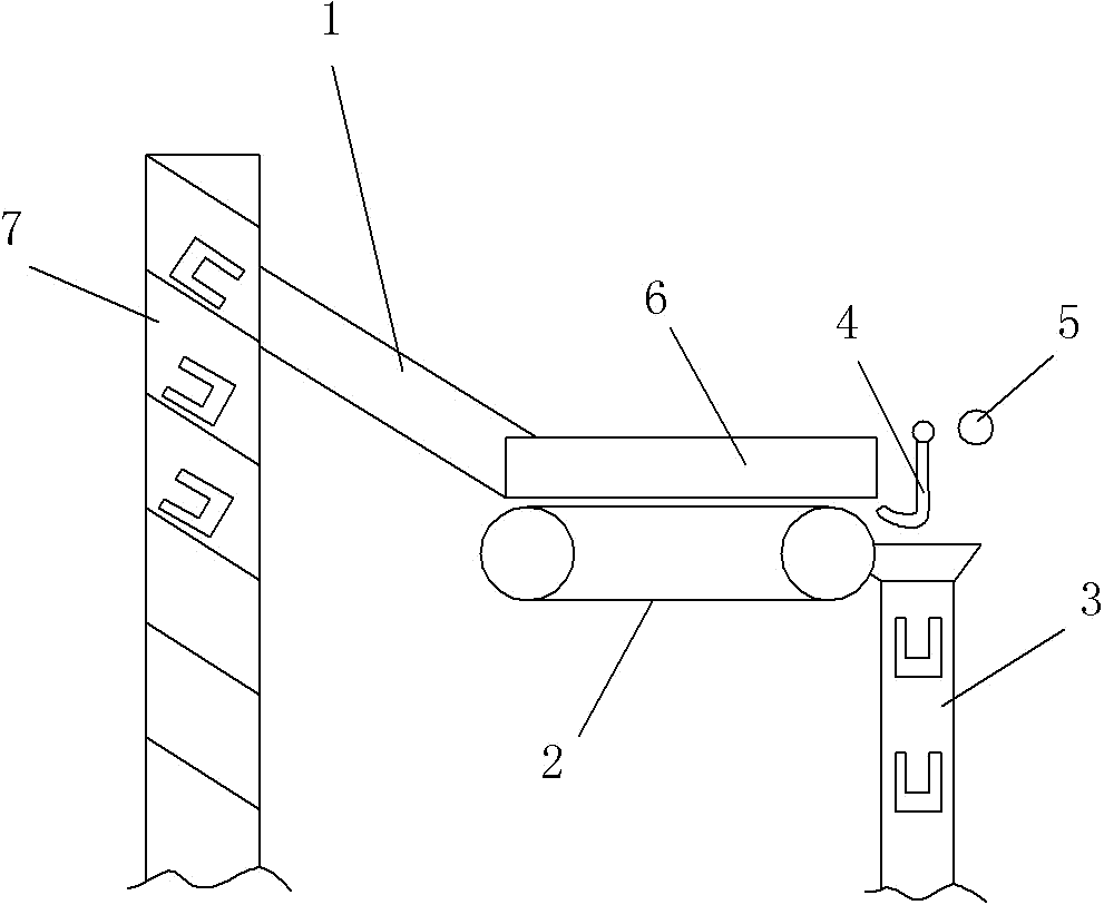
[0010] The reference signs in the drawings of the specification include: feeding chute 1, conveyor belt 2, orientation groove 3, swing hook 4, stop pin 5, baffle plate 6, elevator 7

[0011] Below in conjunction with accompanying drawing and embodiment the technical solution of the present invention is further described:

[0012] Such as figure 1 As shown, the present invention provides a kind of directional conveying mechanism of workpiece with holes on the end face, comprising feeding chute 1, conveyor belt 2 and directional groove 3, the outlet of feeding chute 1 is close to the input end of conveyor belt 2, and directional groove 3 is arranged on The output end of the conveyor belt 2 is also provided with a swing hook 4 above the orientation groove 3, and the curved free end of the swing hook 4 faces the conveying direction of the conveyor belt 2. A stop pin 5 is arranged behind the swing hook 4, and the stop pin 5 is positioned at the side of the orientation groove 3. Ab...


PUM


Abstract

The invention discloses a transportation device, and particularly relates to an orientation transmission mechanism for a workpiece with an end face with a hole. The orientation transmission mechanism comprises a feeding chute, a transmission belt and an orientation groove, an outlet of the feeding chute is close to an input end of the transmission belt, the orientation groove is formed in an output end of the transmission belt, a swing hook is arranged above the orientation groove, a bent free end of the swing hook faces the conveying direction of the transmission belt, a stop pin is arranged behind the swing hook and positioned above an opening of the orientation groove, and the stop pin and a suspension point of the swing hook are positioned at the same height. By the aid of the technical scheme, the orientation transmission mechanism for the workpiece with the end face with the hole is simple in structure, and the workpiece can be transmitted in an oriented manner.

Description

technical field [0001] The invention relates to a transportation device, in particular to a directional transmission mechanism for workpieces with holes on their ends. Background technique [0002] In the machinery manufacturing industry, a large number of parts need to be processed and transported. A workpiece with a hole on one end is a very common part to be processed in mechanical processing. The asymmetric shape of its two ends requires it to be placed neatly and uniformly when it is to be processed and transmitted. However, at present, it is placed manually This method not only leads to inefficiency, but also increases labor costs. Contents of the invention [0003] The technical problem to be solved by the present invention is that in the prior art, the directional transmission of workpieces with holes on one end surface cannot be realized, manual placement is required, and the transmission efficiency is low. [0004] In order to solve the above technical problems...

Claims


Application Information

Patent Timeline
IPC IPC(8): B65G47/34B65G47/74B65G47/04B65G21/20
Inventor 姜静慧
Owner CHONGQING MING SHIELD ELECTROMAGNETIC VALVE
Why Eureka
Try Eureka