
Underground gasification device and underground gasification method

An underground gasification and gasification agent technology, which is applied in coal gasification, underground mining, construction, etc., can solve the problems that the gasification agent cannot effectively gasify the working face and the preheating effect is limited.

Inactive Publication Date: 2014-04-30
ENN SCI & TECH DEV
View PDF6 Cites 7 Cited by
  • Summary
  • Abstract
  • Description
  • Claims
  • Application Information

AI Technical Summary

Problems solved by technology

In the prior art, the defect is that although the mixed transportation of various gasification agents is realized, the gasification agent cannot be guaranteed to reach the effective gasification working face, and the preheating effect is limited

Method used


Image

  • Underground gasification device and underground gasification method
  • Underground gasification device and underground gasification method

Examples


Embodiment Construction

[0019] The underground gasification device and underground gasification method of the present invention will now be described with reference to the accompanying drawings.

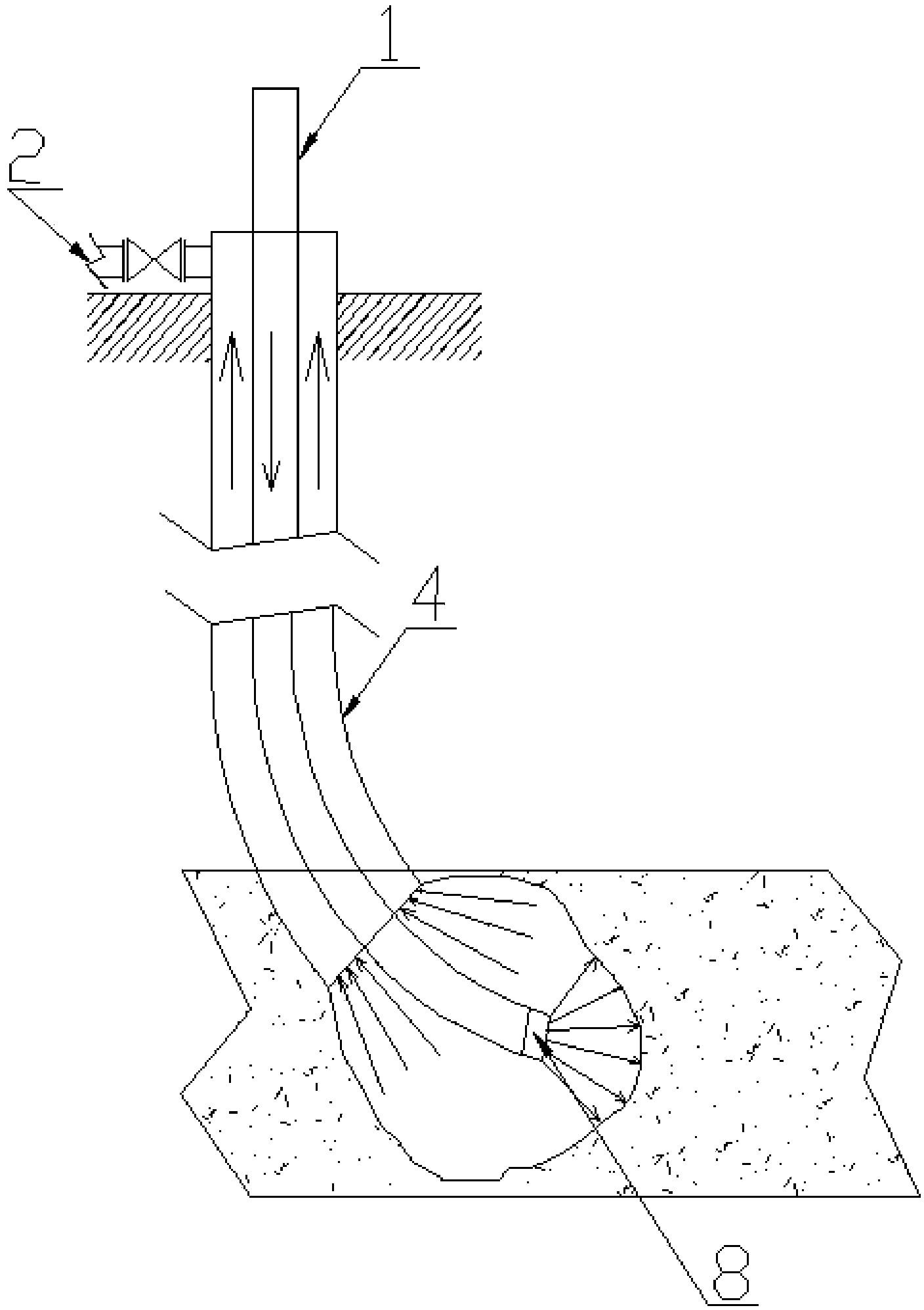
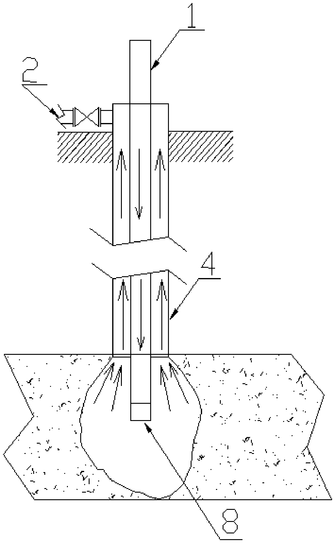
[0020] Such as figure 1 Shown is an embodiment of the underground gasification device of the present invention, which includes a drilling casing 4, a gas injection pipe 1 and a power drive device. Wherein, the first end of the drilling casing 4 is a closed end, and the second end is an open free end. Further, the gas injection pipe 1 extends into the drilling casing 4 from the first end and extends out from the second end, and the gas injection pipe 1 is used for introducing gasification agent into the underground gasification zone.

[0021] Specifically, during the actual application of the underground gasification device of the present invention, the gasification agent can be introduced from the gas injection pipe 1 and sprayed out from the end of the gas injection pipe 1 protruding from the open end of ...


PUM


Abstract

The invention provides an underground gasification device comprising a drilling sleeve (4), a gas injection pipe (1) and a power driving device. The first end of the drilling sleeve (4) is a closed end, and the second end of the drilling sleeve (4) is an open free end. The gas injection pipe (4) extends into the drilling sleeve (4) from the first end and extends out of the drilling sleeve (4) from the second end. The power driving device drives the gas injection pipe (1) to move along the extension direction of the drilling sleeve (4). The invention further provides an underground gasification method. By the underground gasification device and the underground gasification method, gasification agents and organic matters in underground gasification areas are at least ensured to always react with each other through movement of the gas injection pipe.

Description

technical field [0001] The invention relates to an underground gasification device and an underground gasification method. Background technique [0002] The traditional gasification process in solid organic matter requires mechanically processing channels in advance, or constructing channels through physical or chemical methods, and further processing channels or gasification in the already formed channels. At the same time, gasification agents and high-temperature gas cannot Effective heat transfer. Even if some gasification processes have no gasification channels, the gasification process can only be gasified near the gas injection point because the gas injection point cannot be moved, and the gasification process will not last for a long time because the gasification agent will not completely reach the gasification working face. Maintain high calorific value gas. [0003] The Chinese invention patent with publication number 102486085A discloses a gasification agent deli...

Claims


Application Information

Patent Timeline
Patent Type & Authority Applications(China)
IPC IPC(8): E21B43/295
Inventor 桂谢文刘洪涛潘霞
Owner ENN SCI & TECH DEV
Learn More