
Optical film locating device

一种光学膜片、定位装置的技术,应用在光学、照明装置、光源固定等方向,能够解决暗影、光学膜片变形弯曲、影响背光模组成像品质等问题,达到提高品质、保证平整度的效果

Active Publication Date: 2014-04-30
TCL CHINA STAR OPTOELECTRONICS TECH CO LTD
View PDF5 Cites 14 Cited by
  • Summary
  • Abstract
  • Description
  • Claims
  • Application Information

AI Technical Summary

Problems solved by technology

In the existing optical diaphragm, there are multiple positioning holes, and the shape of each positioning hole is compatible with the positioning column. Under the condition of high temperature and high humidity, the optical diaphragm will expand with heat and contract with cold. , the optical film interferes between the positioning post and the positioning hole at the positioning position, causing the optical film to deform and bend, which greatly affects the installation and use of the optical film, and then affects the imaging quality of the backlight module. Phenomena such as shadows appear

Method used


Image

  • Optical film locating device
  • Optical film locating device

Examples


Embodiment Construction

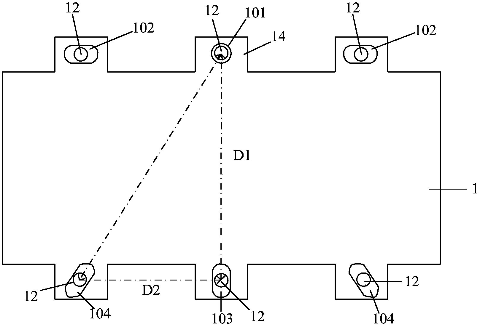
[0012] In order to strengthen the positioning of the optical diaphragm, and to avoid the interference of the positioning column with the positioning hole when the optical diaphragm expands with heat and contracts with cold, to ensure the smoothness of the optical diaphragm, refer to figure 1 As shown, the present invention provides a positioning device for an optical film, comprising a positioning hole 10 provided on the optical film 1 and a positioning post 12 inserted into the positioning hole 10, through which the positioning post 12 passes through the positioning hole 10, and the The optical film 1 is fixed on the carrier substrate, and the shapes of the positioning holes 10 respectively extend in the contraction and expansion directions of the corresponding positions of the optical film 1 .

[0013] The optical film 1 is suitable for a backlight module, such as a diffusion sheet, a prism sheet, an enhancement film, etc., to improve the brightness and taste of the backlight...


PUM


Abstract

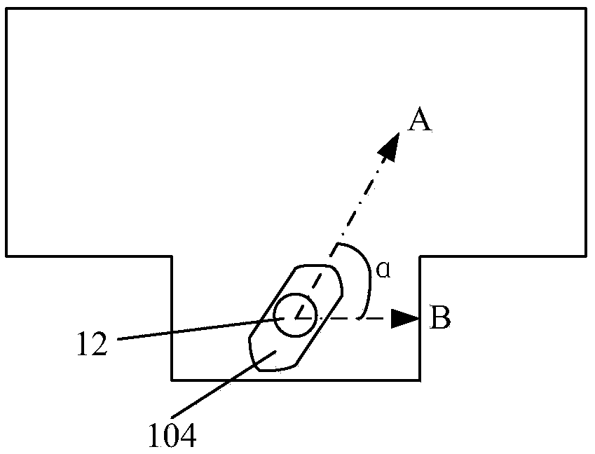
The invention provides an optical film locating device which comprises locating holes formed in an optical film and locating columns inserted into the locating holes. The locating columns penetrate through the locating holes, so that the optical film is fixed on a bearing substrate. The optical film locating device is characterized in that the shapes of the locating holes respectively extend in the shrinkage and expansion direction of the optical film in the corresponding position, the locating holes different in shape are formed in the periphery of a fixing hole of the locating device, the extending direction of a long shaft of the locating holes in the point is the same as the shrinkage and expansion direction of the optical film, the width of the extending direction of the long shaft of the locating holes is larger than the diameter of the locating columns, certain widths are reserved in the locating holes, so that the optical film is made to shrink and expand freely in respective locating points, the locating columns cannot interfere the locating holes to cause bending deformation at the expansion and Contraction time of the optical film, and the levelness of the optical film is ensured, so that the quality of a backlight module is improved.

Description

technical field [0001] The invention relates to an optical component of a backlight module, in particular to a positioning device for an optical film. Background technique [0002] The optical film is used in the backlight module to increase the brightness of the backlight module. Since the film is thin, it needs to be positioned by mechanism design. In the existing optical diaphragm, there are multiple positioning holes, and the shape of each positioning hole is compatible with the positioning column. Under the condition of high temperature and high humidity, the optical diaphragm will expand with heat and contract with cold. , the optical film interferes between the positioning post and the positioning hole at the positioning position, causing the optical film to deform and bend, which greatly affects the installation and use of the optical film, and then affects the imaging quality of the backlight module. Phenomena such as shadows appear. Contents of the invention ...

Claims


Application Information

Patent Timeline
Patent Type & Authority Applications(China)
IPC IPC(8): F21V17/10
CPCF21V17/002G02F1/133606G02F2201/46G02F2201/54F21V17/108G02B5/02G02F1/133608
Inventor 贺虎
Owner TCL CHINA STAR OPTOELECTRONICS TECH CO LTD
Learn More