Flat electrode supported ceramic electrolyte battery and preparation method thereof

A ceramic electrolyte, flat-plate technology, used in solid electrolyte fuel cells, fuel cells, battery electrodes, etc., can solve the problems of difficult to obtain materials, low battery strength, and difficult production, to reduce the preparation cost, improve the battery strength, The effect of simplifying the preparation process

Active Publication Date: 2016-10-19
NINGBO INST OF MATERIALS TECH & ENG CHINESE ACADEMY OF SCI +1
View PDF6 Cites 30 Cited by
  • Summary
  • Abstract
  • Description
  • Claims
  • Application Information

AI Technical Summary

Problems solved by technology

However, due to the particularity of the operating environment of ceramic electrolyte batteries, the requirements for this type of electrode material are extremely high, not only anti-oxidation, but also anti-reduction. In addition, the life and performance of the material itself must be considered, so this type of material hard to get
Even if such materials are obtained, the battery still has problems such as low strength, difficulty in production, and easy large fragmentation.

Method used


Image

  • Flat electrode supported ceramic electrolyte battery and preparation method thereof
  • Flat electrode supported ceramic electrolyte battery and preparation method thereof

Examples


Embodiment 1

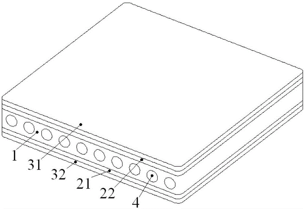
[0041] In this embodiment, the schematic diagram of the structure of the ceramic electrolyte battery supported by flat electrodes is as follows figure 1 As shown, the supporting electrode layer 1, the electrolyte layer and the unsupported electrode layer are stacked up and down along the thickness direction, the supporting electrode is an anode, and the unsupported electrode is a cathode. The electrolyte layer includes a first electrolyte layer 21 and a second electrolyte layer 22 , the first electrolyte layer 21 is located on the upper surface of the supporting electrode layer 1 , and the second electrolyte layer 22 is located on the lower surface of the supporting electrode layer 1 . The unsupported electrode layer includes an upper first unsupported electrode layer 31 and a second unsupported electrode layer 32, the first unsupported electrode layer 31 is located on the upper surface of the first electrolyte layer 1, and the second unsupported electrode layer 32 is located o...

Embodiment 2

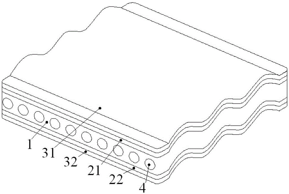
[0053] In this embodiment, the schematic diagram of the structure of the ceramic electrolyte battery supported by flat electrodes is as follows figure 2 shown. The structure is the same as figure 1 The structures shown are basically the same, except that the upper and lower surfaces of the supporting electrode layer 1, the upper and lower surfaces of the first electrolyte layer 21, the upper and lower surfaces of the second electrolyte layer 22, the upper and lower surfaces of the first unsupported electrode layer 31, and the second The upper and lower surfaces of the non-supporting electrode layer 32 are both uneven and wavy.


PUM

PropertyMeasurementUnit
thicknessaaaaaaaaaa
thicknessaaaaaaaaaa
thicknessaaaaaaaaaa

Abstract

The invention provides a flat electrode supported ceramic electrolyte battery. The structure of the battery is a vertical distribution type and takes a supporting electrode layer as the center. The supporting layer has a hollow porous structure. The side surface of the supporting layer is provided with an opened end, through which air can be introduced into the hollow holes. Compared with the prior art, when the flat electrode supported ceramic electrolyte battery runs, three phase boundaries where electrochemical reactions happen are arranged on the upper side and low side of the supporting electrode layer, thus generated thermal stress is effectively neutralized, thermal stress is largely reduced, the thermal damage to electrolyte and electrode is avoided, and the flatness of battery during the battery sintering process can be maintained. When the supporting electrode layer has a large thickness, the battery size is increased, the battery strength is enhanced, moreover, the preparation technology is simplified, and the preparation cost is reduced.

Description

technical field [0001] The invention relates to the technical field of ceramic electrolyte batteries, in particular to a flat electrode-supported ceramic electrolyte battery and a preparation method thereof. Background technique [0002] A ceramic electrolyte battery is a highly efficient energy conversion device. Its basic structure includes a dense ceramic electrolyte, a porous anode and a porous cathode. The chemical reaction produces electrons, which form an external electronic circuit, which ultimately produces electricity and heat. Flat ceramic electrolyte battery is a main structure of this type of battery at present. According to the classification of strength support, flat ceramic electrolyte batteries mainly include three types: electrolyte support, anode support and cathode support. In order to reduce the working temperature, the electrode support type has been developed rapidly and formed a wide range of applications. [0003] However, the existing electrode-s...

Claims


Application Information

Patent Timeline
Patent Type & Authority Applications(China)
IPC IPC(8): H01M8/12H01M4/86
CPCH01M4/8621H01M8/1246Y02E60/50
Inventor 官万兵王建新王泽深丁飞桑林
Owner NINGBO INST OF MATERIALS TECH & ENG CHINESE ACADEMY OF SCI
Why Eureka
Try Eureka