H-shaped four-crawler-belt slipform paver

A slip-form paver and four-track technology, which is applied to roads, road repairs, roads, etc., can solve the problem of ensuring the stability and smoothness of the main machine driving and paving operations, and the most effective match between machine quality and driving force , Unfavorable problems such as uniform distribution of machine quality, to achieve the effect of fast and convenient replacement of cutter wheel, flexible and diverse adjustment methods, and simple structure

Active Publication Date: 2014-08-20
山东万顺机械制造有限公司
View PDF5 Cites 32 Cited by
  • Summary
  • Abstract
  • Description
  • Claims
  • Application Information

AI Technical Summary

Problems solved by technology

[0002] Four-track sliding mode cement concrete paver (sliding form paver for short), which integrates concrete distribution, metering, vibration, sliding form extrusion, flat rubbing, and smoothing, can be automatic, high-quality, and once The concrete material is poured and formed on the subgrade; the width of the chassis and the height from the ground are usually adjusted at any time according to the construction requirements; the existing slip mode paver can only extend or retract the two crawlers on one side at the same time To realize the adjustment of the width of the main frame, the overall center of gravity of the sliding form paver will change accordingly after adjustment, and the sliding form mold fixed on the chassis should also be adjusted to re-balance the center of gravity of the chassis; otherwise, during the paving process, It is easy to cause the machine to fall to one side, it is difficult to ensure the stability and smoothness of the main engine's driving and paving operation, it is not conducive to the even distribution of the machine mass to the walking system, and it is difficult to achieve the most effective match between the machine mass and the driving force of the machine. loss; when encountering a special situation where only one track can be extended or retracted, the existing slip mode paver is not up to the task

Method used


Image

  • H-shaped four-crawler-belt slipform paver
  • H-shaped four-crawler-belt slipform paver
  • H-shaped four-crawler-belt slipform paver

Examples


Embodiment 1

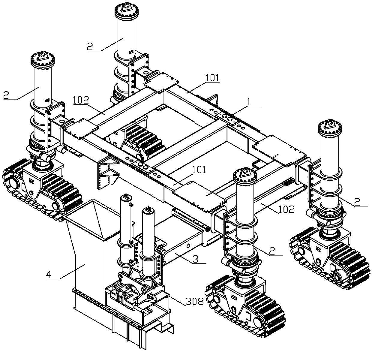
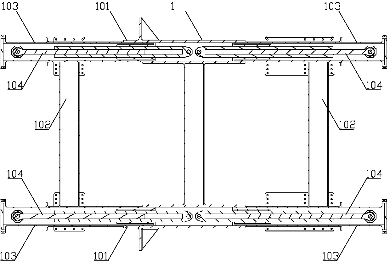
[0042] Embodiment 1: as figure 1 As shown, the H-type four-track slipform paver includes an H-type telescopic chassis 1 and a crawler-type lifting and steering device 2, such as figure 2 As shown, the H-shaped telescopic chassis 1 includes two hollow longitudinal main beams 101, two transverse main beams 102, and four hollow telescopic beams 103; Two transverse main beams 102 are respectively fixed between the top ends, two longitudinal main beams 101 and two transverse main beams 102 form a square frame-shaped main body, and telescopic beams are movably inserted at both ends of each longitudinal main beam 101 103, one end of each telescopic beam 103 is placed in the inner cavity of the longitudinal main beam 101; the outer end of each telescopic beam 103 is provided with a crawler lifting steering device 2; each telescopic beam 103 is provided with a telescopic beam oil cylinder 104, The top of the piston rod of the telescopic beam oil cylinder 104 is fixedly connected with...

Embodiment 2

[0043] Embodiment 2: as Figure 12 As shown, the H-type four-track slipform paver includes an H-type telescopic chassis 1 and a crawler-type lifting and steering device 2. The H-type telescopic chassis 1 includes two hollow longitudinal main beams 101, two transverse main beams 102, Four hollow telescopic beams 103; between two longitudinal main beams 101 bottoms, a side-mounted sliding form mold holder 3 is fixed; its overall structure is the same as in embodiment 1, and the difference is that, as Figure 13 with 14 As shown, the piston rod of the lifting cylinder 302 stretches out upwards, and the sliding form fixture is an upper suspension sliding form fixture 320, such as Figure 15As shown, the upper hanging sliding form fixture 320 includes a fixture bottom plate 321, a movable splint B322, a splint limit block B323, a fixture cylinder B324, and a sliding form connecting plate B325; the bottom of the fixture bottom plate 321 and the piston rod of the lifting cylinder 30...

Embodiment 3

[0044] Embodiment 3: as Figure 16 with 17 As shown, the H-type four-track slipform paver includes an H-type telescopic chassis 1 and a crawler-type lifting and steering device 2. The H-type telescopic chassis 1 includes two hollow longitudinal main beams 101, two transverse main beams 102, Four hollow telescopic beams 103; between the bottoms of the two longitudinal main beams 101, a side-mounted sliding form mold holder 3 is fixed; A material conveyor fixing frame 5 is fixed between one end of the beam 101; Figure 18 As shown, the material conveyor fixed frame 5 includes a fixed frame main beam 501, a fixed frame movable arm 502, a fixed frame oil cylinder 503, and a conveyor connecting seat 504. The fixed frame main beam 501 is fixed on the bottom of the two longitudinal main beams 101, One end of the fixed frame movable arm 502 is slidingly inserted in the fixed frame main beam 501, and the outer end of the fixed frame movable arm 502 is vertically provided with a conve...


PUM


Abstract

A disclosed H-shaped four-crawler-belt slipform paver comprises an H-shaped telescopic chassis and crawler-type elevating turning apparatuses; the H-shaped telescopic chassis comprises two hollow longitudinal main beams, two transverse main beams and four hollow telescopic beams; the two transverse main beams are fixedly disposed between the top ends of the two longitudinal main beams; each of two ends of each longitudinal main beam is flexibly connected with the telescopic beam in an insertion manner; each telescopic beam is inside provided with a telescopic-beam oil cylinder; the top end of a piston rod of the telescopic-beam oil cylinder is connected with the telescopic beam, and the cylinder body of the telescopic-beam oil cylinder is fixedly connected with the longitudinal main beam; and the outer end of each telescopic beam is provided with the crawler-type elevating turning apparatus. The H-shaped four-crawler-belt slipform paver has the advantages that the four telescopic beams can have individual telescopic adjustment or have optionally-combined telescopic adjustment, so that the steady of the chassis and the paving flatness are guaranteed, the telescopic resistance of the telescopic beams is small, the adjustment manners are flexible and various, the application scope is wide, and the chassis can be adjusted into optional inclined angle according to different construction cases.

Description

Technical field: [0001] The invention relates to road engineering equipment, in particular to an H-type four-crawler sliding form paver. Background technique: [0002] Four-track sliding mode cement concrete paver (sliding form paver for short), which integrates concrete distribution, metering, vibration, sliding form extrusion, flat rubbing, and smoothing, can be automatic, high-quality, and once The concrete material is poured and formed on the subgrade; the width of the chassis and the height from the ground are usually adjusted at any time according to the construction requirements; the existing slip mode paver can only extend or retract the two crawlers on one side at the same time To realize the adjustment of the width of the main frame, the overall center of gravity of the sliding form paver will change accordingly after adjustment, and the sliding form mold fixed on the chassis should also be adjusted to re-balance the center of gravity of the chassis; otherwise, dur...

Claims


Application Information

Patent Timeline
Patent Type & Authority Applications(China)
IPC IPC(8): E01C19/48
CPCE01C19/4893
Inventor 陈建军
Owner 山东万顺机械制造有限公司
Why Eureka
Try Eureka