Plate heat exchanger

A plate heat exchanger and heat exchange plate technology are used in the fields of automobiles, refrigeration, transportation, and HVAC, which can solve the problems that the heat exchange plate is difficult to obtain fluid distribution, affects the overall performance of the evaporator, and is difficult to evenly distribute the refrigerant. , to achieve consistent and stable process and performance, good fluid distribution, cost reduction

Inactive Publication Date: 2014-04-30
DANFOSS MICRO CHANNEL HEAT EXCHANGER JIAXING
View PDF16 Cites 32 Cited by
  • Summary
  • Abstract
  • Description
  • Claims
  • Application Information

AI Technical Summary

Problems solved by technology

Usually the refrigerant entering the heat exchanger exists in the form of two phases, due to the application conditions and the complexity of the two-phase flow, it is difficult to achieve uniform distribution of the refrigerant
In many cases, excess liquid refrigerant will flow into some channels, while too much gaseous refrigerant will flow into other channels, which will greatly affect the overall performance of the evaporator.
[0003] However, it is difficult to obtain good fluid distribution for such a large heat exchange plate because the heat exchange plate is too wide, for example along the lengthwise direction of the heat exchange plate

Method used


Image

  • Plate heat exchanger
  • Plate heat exchanger
  • Plate heat exchanger

Examples


Embodiment Construction

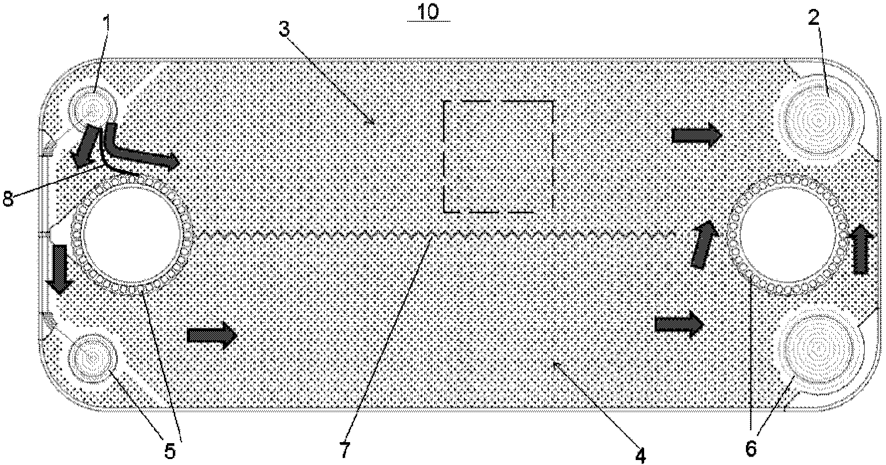
[0047] Through the following examples, combined with the attached Figure 1-10b , the technical solution of the present invention will be further specifically described. In the specification, the same or similar reference numerals designate the same or similar components. The following description of the embodiments of the present invention with reference to the accompanying drawings is intended to explain the general inventive concept of the present invention, but should not be construed as a limitation of the present invention.

[0048] see figure 1 , shows a front view of a heat exchange plate 10 in a plate heat exchanger according to an embodiment of the present invention. As known to those skilled in the art, a plate heat exchanger includes a plurality of heat exchange plates 10 stacked on top of each other, and end plates (not shown) arranged on the outer side of the plate heat exchanger for fixing The heat exchange plate 10. That is, a plurality of stacked heat exch...


PUM


Abstract

The invention provides a plate heat exchanger. The plate heat exchanger comprises a plurality of heat exchange plates, wherein the heat exchange plates are overlaid with one another, and each heat exchange plate is provided with a fluid inlet and a fluid outlet which are located in the two opposite ends of the heat exchange plate respectively in the lengthwise direction. A partition part is arranged on the upper surface and / or the lower surface of each heat exchange plate, so that fluid from the fluid inlets is divided at the fluid inlets, then flows into independent fluid passage zones partitioned by the partition parts, gathers at the fluid outlets and flows out of the fluid outlets at last.

Description

technical field [0001] The invention relates to the fields of HVAC, automobile, refrigeration and transportation, and in particular to a plate heat exchanger. Background technique [0002] For parallel-channel heat exchangers (evaporators), especially plate heat exchangers and micro-channel heat exchangers, refrigerant mal-distribution is a worldwide technical problem. Usually, the refrigerant entering the heat exchanger exists in the form of two phases. Due to the application conditions and the complexity of the two-phase flow, it is difficult to achieve uniform distribution of the refrigerant. In many cases, excess liquid refrigerant will flow into some channels, while too much gaseous refrigerant will flow into other channels, which will greatly affect the overall performance of the evaporator. [0003] However, since the heat exchange plate is too wide, it is difficult to obtain good fluid distribution for such a large heat exchange plate, for example along the lengthwi...

Claims


Application Information

Patent Timeline
Patent Type & Authority Applications(China)
IPC IPC(8): F25B39/02F28F9/22
CPCF28F13/06F28D9/0043F28D9/005F28D2021/0064F28D2021/0071F28F3/044F28F3/086F28F3/10F28F9/026F28F9/22
Inventor 魏文建张志锋徐阳
Owner DANFOSS MICRO CHANNEL HEAT EXCHANGER JIAXING
Why Eureka
Try Eureka