Radio communication system and control method of radio resource allocation

a radio communication system and radio resource technology, applied in the field of radio communication system, can solve problems such as low signal quality, and achieve the effect of efficient radio resource allocation

Inactive Publication Date: 2013-04-11
NEC CORP
View PDF3 Cites 28 Cited by
  • Summary
  • Abstract
  • Description
  • Claims
  • Application Information

AI Technical Summary

Benefits of technology

[0014]As described above, according to the present invention, it is possible to achieve efficient radio resource allocation in a relay network.

Problems solved by technology

One of the main objectives for deploying RNs is to enhance coverage area of a base station by improving throughput of a mobile station (user terminal) that locates in a coverage hole or far from the base station resulting in low signal quality.

Method used


Image

  • Radio communication system and control method of radio resource allocation
  • Radio communication system and control method of radio resource allocation
  • Radio communication system and control method of radio resource allocation

Examples


first exemplary embodiment

3. First Exemplary Embodiment

3.1) Outline

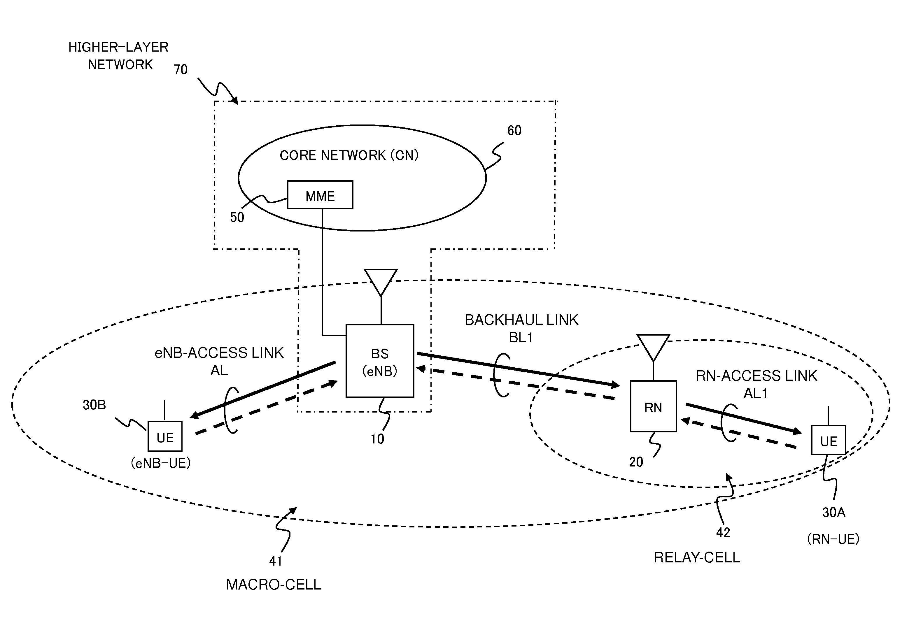
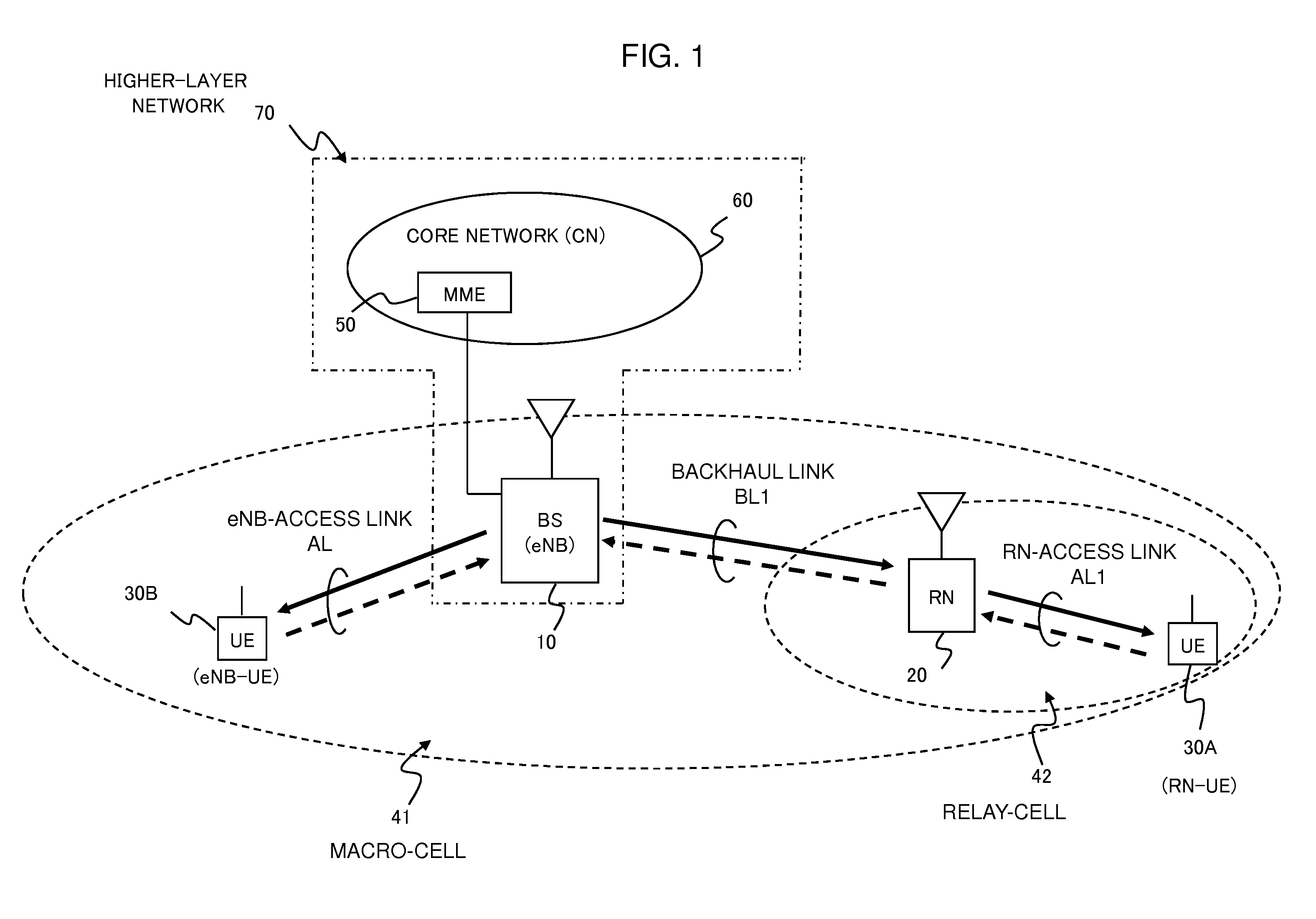
[0069]Referring to FIG. 6, the higher-layer network 70 including the DeNB 10 configures the RN 20 to set a target value for a predetermined parameter reflecting both statuses of the backhaul link BL1 and the RN-access link AD (SETTING). The predetermined parameter may be the amount of data stored in the RN 20 to be transmitted to the RN-UE 30A, a throughput ratio between the backhaul link BL1 and the RN-access link AL1, a throughput difference between the backhaul link BL1 and the RN-access link AL1, or another parameter related to both the backhaul link BL1 and the RN-access link AL1. The target value is pre-decided as a threshold for desired performance corresponding to QoS (Quality of Service) of UE or a requirement of system operator.

[0070]The scheduler 206 of the RN 20 as shown in FIG. 3 monitors the predetermined parameter to obtain a monitored parameter value at preset timing or predetermined intervals. The scheduler 206 compares the s...

second exemplary embodiment

4. Second Exemplary Embodiment

[0086]While the first exemplary embodiment shows the case of the DeNB 10 using the pre-decided target value for configuring the RN 20, a second exemplary embodiment shows a case of the DeNB 10 determining the target value based on link information related to the backhaul and RN-access links (backhaul link information and RN-access link information, respectively, in the following). In the following, detailed operations of an example of Embodiment 2 will be explained by employing FIG. 10 and FIG. 11.

[0087]FIG. 10 shows an exemplary sequence diagram of the DeNB 10 determining and transmitting the target value to the RN 20 based on the change in the number of RN-UEs, and changing the backhaul link parameter based on the difference information provided by the RN 20. Here, it is assumed that there are two RN-UEs (RN-UE1 and RN-UE2) in the network initially not connecting with the RN 20.

[0088]Referring to FIG. 10, step S1401 shows RN-UE1 establishing connectio...

third exemplary embodiment

5. Third Exemplary Embodiment

[0097]While the first exemplary embodiment shows the case of the DeNB 10 using the pre-decided target value for configuring the RN 20, a third exemplary embodiment shows a case of the DeNB 10 modifying the target value based on link information related to throughput of the RN-access link provided by the RN 20 (RN-access link throughput information in the following). In the following, detailed operations of an example of the third exemplary embodiment will be explained by referring to FIGS. 12-14.

[0098]FIG. 12 shows an exemplary sequence diagram of the DeNB modifying the pre-decided target value based on the RN-access link throughput information provided by the RN 20, and changing the backhaul link parameter based on the difference information provided by the RN 20.

[0099]Referring to FIG. 12, step S1601 to S1608 are the same as step S1101 to S1108 of FIG. 7 as described above, which show the DeNB 10 configuring the RN 20 with the pre-decided target value,...


PUM


Abstract

A communication system includes a plurality of nodes including a base station; at least one terminal; and at least one relay node through which each terminal can be connected to the base station. An entity in a network higher in layer than each relay node configures the relay node to set a target value for a predetermined parameter reflecting a radio link status of the relay node. The relay node monitors the predetermined parameter to notify an upper-layer node of difference information corresponding to a difference between the target value and a monitored parameter value. The upper-layer node controls a link parameter of a radio link connecting the upper-layer node and the relay node depending on the difference information, resulting in efficient radio resource allocation in a relay network with small signaling overhead.

Description

TECHNICAL FIELD[0001]The present invention relates to a radio communication system employing relay nodes, and more particularly to a technique of controlling radio resource allocation in the radio communication system.BACKGROUND ART[0002]3GPP (3rd Generation Partnership Project) LTE-Advanced (Long Term Evolution Advanced) Study Item considers deploying relay node (hereafter referred to as RN) in a cellular network. One of the main objectives for deploying RNs is to enhance coverage area of a base station by improving throughput of a mobile station (user terminal) that locates in a coverage hole or far from the base station resulting in low signal quality. Hereafter, a base station is referred to as BS or eNB (evolved Node B) and a mobile station or user terminal is referred to as UE (user equipment).[0003]In the radio communication network with relay nodes, an eNB that can provide connection to at least one RN is called Donor eNB, which is hereafter called DeNB. In this specificatio...

Claims


Application Information

Patent Timeline
Patent Type & Authority Applications(United States)
IPC IPC(8): H04W72/08H04B7/15
CPCH04W84/047H04B7/15H04W72/04H04W28/18H04W72/085H04B7/2606H04W72/542
Inventor PITAKDUMRONGKIJA, BOONSARNAMINAKA, HIROAKIKAKURA, YOSHIKAZU
Owner NEC CORP
Why Eureka
Try Eureka