
Device for testing dynamic friction torque of air static-pressure axial thrust bearing

An axial thrust bearing and thrust bearing technology, which is used in measuring devices, force/torque/work measuring instruments, instruments, etc., to reduce radial friction and obtain accurate results.

Inactive Publication Date: 2014-04-30
SHANGHAI UNIV
View PDF4 Cites 24 Cited by
  • Summary
  • Abstract
  • Description
  • Claims
  • Application Information

AI Technical Summary

Problems solved by technology

[0005] Aiming at the shortage of dynamic friction torque of thrust bearings formed by testing air bearings at present, the present invention provides a testing device for dynamic friction torque of aerostatic axial thrust bearings

Method used


Image

  • Device for testing dynamic friction torque of air static-pressure axial thrust bearing
  • Device for testing dynamic friction torque of air static-pressure axial thrust bearing
  • Device for testing dynamic friction torque of air static-pressure axial thrust bearing

Examples


Embodiment 1

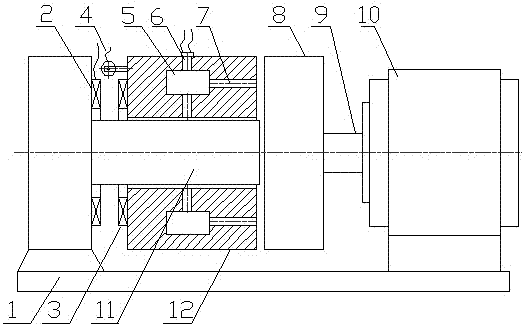
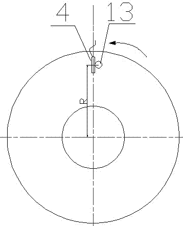
[0020] see Figure 1~Figure 4 , the aerostatic axial thrust bearing dynamic friction torque testing device, including base 1, energized coil 2, permanent magnet 3, force sensor 4, thrust plate 8, main shaft rotor 9, electric main shaft 10, supporting shaft 11 and a The measured radial air bearing 12 is characterized in that the radial air bearing 12 is installed on the support shaft 11, the support shaft 11 is disconnected from the thrust plate 8, and on the end face of the radial air bearing 12 , a pressure rod 13 is placed, and the protruding section of the pressure rod 13 is pressed on the installed force sensor 4; the radial air bearing thrust bearing 12 is axially loaded by a non-contact electromagnetic loading device, and one end of the base 1 is fixed The coil 2 that can be energized, the end face of the radial air bearing 12 is fixed with a permanent magnet 3, when the coil 2 is energized, the coil acquires magnetism, and the magnetism is the same as that of the opposi...

Embodiment 2

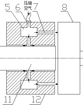
[0022] Such as figure 1 As shown, the aerostatic axial thrust bearing dynamic friction torque testing device is mainly composed of a base 1, a energized coil 2, a permanent magnet 3, a force sensor 4, an annular groove 5, a radial closure hole 6, and an axial closure hole 7 , Thrust plate 8, main shaft rotor 9, electric main shaft 10, support shaft 11, radial air bearing thrust bearing 12, pressure bar 13 etc. composition. The support shaft 11 is fixed on the machine base 1, the radial air bearing thrust bearing 12 to be tested is installed on the support shaft 11, and the electric spindle 10 is used as a driving device. The main shaft rotor 9 is connected with the thrust plate 8, and the thrust plate 8 is disconnected from the radial air bearing 12. On the end face of the air bearing 12, a pressure rod 13 is placed, and the protruding section of the pressure rod 13 is pressed on the installation on the force sensor 4.

[0023] Such as figure 2 As shown, the compressed air...


PUM


Abstract

The invention discloses a device for testing dynamic friction torque of an air static-pressure axial thrust bearing. The device for testing dynamic friction torque of the air static-pressure axial thrust bearing comprises an engine base, an electrified coil, a permanent magnet, a force sensor, a thrust collar, a main shaft rotor, an electric main shaft, a supporting shaft, and a radial air thrust bearing to be tested. The radial air thrust bearing is arranged on the supporting shaft, a pressing rod is arranged on the end face of the radial air thrust bearing, and the section extending out the pressing rod is arranged on the force sensor; the radial air thrust bearing loads axially through a non-contact type electromagnetic loading device, the electrified coil is fixed at one end of the engine base, the permanent magnet is fixed on one end face of the radical air thrust bearing, the coil has the magnetism and has the same magnetic characteristics with the permanent magnet, and the radial air thrust bearing is subject to an axial thrust. To obtain the dynamic friction torques under different axial thrusts, the non-contact type electromagnetic loading device is used for axial loading. The non-contract loading way eliminates the influence of friction caused by contact on a testing result.

Description

technical field [0001] The invention discloses a test device for dynamic friction torque of an aerostatic axial thrust bearing, which belongs to the technical field of electromechanical engineering. Background technique [0002] Friction torque is an important performance index of bearings, which is directly related to energy loss, temperature, noise, vibration changes, etc. during bearing operation. [0003] With the high development of modern science and technology, higher and higher requirements are put forward for the performance of precision instruments and precision machinery, and one of the main factors affecting their performance is friction torque. Therefore, it is very important to accurately measure the magnitude of the friction torque. [0004] At present, there are many methods for testing the friction torque of thrust bearings, including direct friction torque measurement method, balance torque method and energy conversion method. The most commonly us...

Claims


Application Information

Patent Timeline
IPC IPC(8): G01L5/00
Inventor 李松生俞锋邵娟黄小泵
Owner SHANGHAI UNIV
Learn More